Tool/software:
Hi,
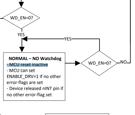
Q1: When watchdog time out, EN_DRV goes low, correct ?
Q2: can it be set just a negative pulse output ?
Q3: can we re-config a PMIC GPIO pulse output when watchdog timeout ?
Q4: watchdog can be cleared by I2C or PMIC GPIO8, correct ?
Thanks
Max