Tool/software:
Hi Team,
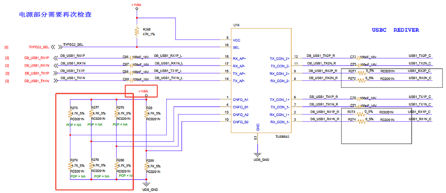
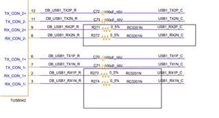
Does TUSB542 has requirement of routing length? I didn't see it in DS.
Original question:

TUSB546-DCI: Cost effective solution without DP ALT function
Tool/software:
Hi Team,
Does TUSB542 has requirement of routing length? I didn't see it in DS.