This thread has been locked.

If you have a related question, please click the "Ask a related question" button in the top right corner. The newly created question will be automatically linked to this question.

TPS2640: Reverse polarity protection is non-functional

Part Number: TPS2640
Other Parts Discussed in Thread: LM60440

Tool/software:

Hi,

We have implemented the TPS2640 (VQFN package) in a design, however, the reverse polarity protection does not work. The other protection features seem to be functioning properly, and I don't measure a short circuit between RTN and GND which the datasheet says will disable the reverse polarity protection. Is there any other way that it might be disabled? From what I can tell our implementation is almost identical to the evaluation circuit.

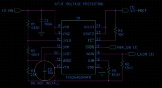
Pins 1-7, 11, 16, and 21 are unconnected. Pin 25 (Pad) is connected to RTN.

PWR_SW goes to a connector and the external switch eventually connects the net to system ground.

I_MON connects to a GPIO on a PIC32 microcontroller.

I considered that these external connections might somehow be influencing the chip, but I built up the eFuse circuit on a bare board without anything else and saw the same behavior.

Thanks,

Kyle.

  • Hello Kyle,

    Have you measured RTN and GND on board? If they are shorted.

    Schematic looks fine to me.

    Please check the connectivity between RTN and GND.

    Thanks 

    Amrit 

  • Hi Armit,

    I can confirm that there is no short between RTN and GND. The resistance between those nets is about 400k.

  • Amrit,

    I have also been doing some PSpice simulations of the circuit and it looks like varying the load has a direct effect on the negative voltage that gets through the circuit. Does this chip have a minimum load requirement?

    The simulations indicate that I need a load of 400 ohms to have a negative voltage of less than 1 volt. This is in contrast to what I see testing the circuit on the bench. I can easily achieve negligible negative output voltage with a 100 kohm load. I am pretty new to PSpice, but I'm a bit wary of this result since it is so different.

  • Hello Kyle,

    How much reverse voltage you are seeing on output.

    Can you probe IN and OUT voltages?

    Let me know if you are getting issue similar to below thread.

    (+) TPS2640: TPS26400: reverse polarity protection - Power management forum - Power management - TI E2E support forums

    Thanks 

    Amrit 

  • Amrit,

    I measured the output voltage under several different load conditions and got the following output. My multimeter input impedance in Lo Z mode is about 3k.

    Vin Vout
    No Load Lo Z Mode 100k load 1 Meg load
    -4 -2.38 0 -0.11 -0.76
    -10 -7.12 0 -0.3 -2.27
    -20 -15.43 0 -0.54 -4.22
    -30 -23.38 0 -0.75 -5.91

    As you can see the results vary significantly based on the value of the load. I agree this is probably just due to leakage through the device not being shunted to ground properly as in the other thread.

    I suppose the question now is how best to deal with it. Is it okay to just put a high value resistor (100-200k) between the TPS2640 Vout and GND to bleed off the excess negative voltage that develops due to leakage?

    On my board the output of this circuit is fed directly to the input of DC-DC converter designed around the LM60440 (block diagram below for reference). The minimum voltage allowed on the input pin is -0.3 V, which would already be exceeded by even -4 V input if we assume the back to back FETs in the device remain off when the input sees a negative voltage, presenting a high impedance to the TPS2640 output.

  • Hello Kyle,

    Thanks for the results.

    Understood your concern. The cap on output has no discharge path which is making output voltage rising in high impedance path.

    You can put a high value resistor at output for discharge in your case. 

    Thanks 

    Amrit