This thread has been locked.

If you have a related question, please click the "Ask a related question" button in the top right corner. The newly created question will be automatically linked to this question.

BQ76907: IC getting damaged upon battery attached

Part Number: BQ76907

Tool/software:

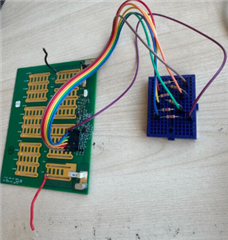
Hello, I am using the BQ76907RGRR in my design. The design is very similar to the dev kit. I have a resistor network set up as well, similar to the dev kit in order to simulate battery cells. I am able to power the board with a power supply hooked up to PACK+ and BAT- at 22V, and I can see the device via I2C. REGOUT is also 3.3V. But when I attach a large battery pack to the setup the IC seems to fail and I can no longer see the device on I2C. The configuration of the battery pack is 6s7p (22.2V). REGOUT is also close to 0V. When I switch back to a power supply, I am still unable to see the device on I2C and REGOUT is still near 0V. Attached are the voltage ramps and inrush current upon battery attach. Is there something that stands out that point to what's damaging the chip? The measurements seem to be under the max ratings in the datasheet. Let me know if there's anything else I can try or test. Thanks!
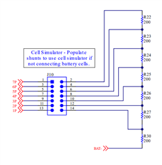
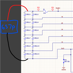
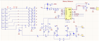
Schematic:

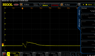
Inrush current. (Used a 10ohm power resistor so inrush current is about 1.74A):

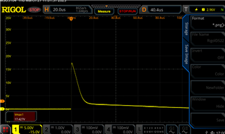
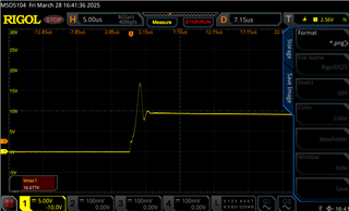
Voltage ramp across DGND and PACK+:

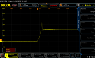
Voltage ramp across DGND and PACK-:

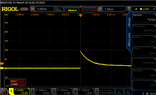
Voltage ramp across DGND and PACK- (Zoomed in):

  • Hello Jerry,

    Do you mind sharing how you are connecting your cells? What is the voltage on the VC0 pin when you connect your cells? The part may have been damaged if you are not able to communicate and see a voltage at the REGOUT pin when switching back to the power supply. 

    While our part support random cell connection, e.g. cell 6 in a 7-cell stack might be first connected, VC0 has a lower voltage tolerance, and its voltage is expected to remain close to the VSS pin voltage during cell attach. If VC0 is not connected through the series resistor to VSS on the PCB, then cells cannot be connected in random sequence. This is stated in a Note in Section 8.2.4 Random Cell Connection Support of the BQ76907 2-Series to 7-Series High Accuracy Battery Monitor and Protector for Li-Ion, Li-Polymer, LiFePO4 (LFP), and LTO Battery Packs datasheet

    Best Regards,
    Alexis

  • Hi Alexis,

    Thanks for the response. I am not connecting individual cells of the battery pack. I have the same resistor network as the dev kit that simulates the different cells of the battery. 

    Then I am just connecting the positive and negative terminals of my battery pack to PACK+ and BAT- respectively.

  • Hello Jerry,

    Thank you for your patience.

    When you connect the positive and negative terminals of your battery pack, are the cell simulator shunts unpopulated/not connected? You do not have the power supply on with the battery pack connected at the same time, correct?

    Do you have a waveform of the VC0 pin? With the transient seen from the waveforms you have shared, the other pins have an abs max up to 40V, however, VC0 only has a maximum voltage of 6V.

    Best Regards,
    Alexis

  • Hi Alexis,

    When I am connecting the positive and negative terminals of my battery pack, the cell simulator shunts ARE populated. I do not have the power supply on with the battery pack connected at the same time.

    I took a capture of the VC0 pin in regards to VSS:

    Looks to be well under the 6V max.

    I've ran a test where I removed the simulator shunts and connected the battery cells one-by-one, and it did not damage the system. But what I'm curious about is why connecting the entire 6S battery pack while using the simulator shunts (similar to how you power up the EVK, except with a power supply) is damaging the balancer.

    Thanks,

    Jerry