This thread has been locked.

If you have a related question, please click the "Ask a related question" button in the top right corner. The newly created question will be automatically linked to this question.

UCC28780: High gain DC-DC converter without auxiliary winding

Part Number: UCC28780

Tool/software:

Hello,

I am currently working on designing a boost converter with a high step-up ratio.
I need an efficient and compact converter, so the active clamp topology caught my attention.
I'm looking into the UCC28780 as it has all the functions I need, but unfortunately my preferred transformer does not have an auxiliary winding.

I'm wondering if it is possible to use this controller without the use of an auxiliary winding and to, for example, use the low voltage primary winding as feedback for the VS pin. As I'm doing step-up and not step down, my primary voltage can be used to directly power the chip on the VDD pin. 

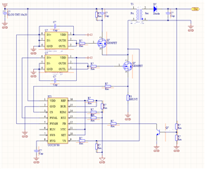
I made a quick rough schematic to make the use case and implementation idea a bit more clear

  • Looks like you don't need isolation since you are using common ground between primary and secondary. So why not just use a regular boost controller?

  • I was looking into using a boost converter, but the needed boost factor is around 30 times, so it isn't suitable for my project unfortunately. I was looking into a topologie with a transformer so I can make use of the ratio to make a high boost factor more doable. Online I saw that the flyback is a pretty popular choice for this kind of boost factors, but I would like to use a rather high switching frequency to keep the footprint rather small so a snubber would be really inefficient. The active clamp flyback seems to meet my requirements but the controller implementation is where I hit a wall.

    Thanks for the reply anyway! I got recommended a few useful topics based on this one which I didn't find before when searching for the UCC28780 
    My question is answer on there as well, thanks

  • Hello Olivier, 

    Yes, I believe that your AUX-less concept can work, but details are needed to verify this expectation.  

    Can you provide numbers for your design targets and turns-ratio, please? 

    Also, your "quick rough schematic" is indeed very rough and several details are missing, incorrect, or overly simplified. 
    1.  SWS input is still needed. 
    2.  VS divider is not correct.
    3.  FB still needs a regulator; I think the single-NPN control may be too crude.
    4.  High-side gate-drive probably can't be powered by the same VDD as low-side driver.  Probably needs a boot-strap arrangement. 
    5.  High-side driver IN+ probably shouldn't be grounded. Slight smile

    However, I get the concept and I see no obvious reason that it couldn't be made to work. 

    Regards,
    Ulrich