This thread has been locked.

If you have a related question, please click the "Ask a related question" button in the top right corner. The newly created question will be automatically linked to this question.

LM5181-Q1: BCM mode switching behaviour at 5.1(V),220(mA) Output

Part Number: LM5181-Q1

Tool/software:

Hi TI Team,

I want to use LM5181-Q1 flyback converter to generate 5.1V output with a 220(mA) maximum load. The input could vary from 12V to 24V (AC-DC)

I have already used the device in an other project to create 13.1V output with 30(mA) and everything works fine; so I tried to use a similar circuit with the same transformer and adapting RFB to optmize the BOM stocked in my factory.

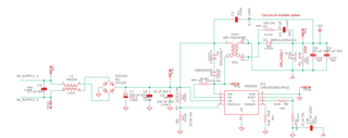
Attached you can see the trial schematic: the transformer used (750318737 Wurth) is present in the datasheet, It is suggested for (5.5 V to 16 V) output range and It has 1:1 ratio.

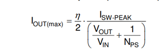
During the test I discovered that at 24V AC (which means about 33V on flyback Vin) If I increase the load over 100 mA the flyback goes in BCM mode; at 220 (mA) of load It reduces the frequency to more or less 200 (Khz)  which reading the datasheet It seems to be the condition of maximum load of  the device (figure 18). Attached you can see the Switching waveform in this condition.

Why does the converter seem to be at maximum load condition at 220 (mA) applied considering that the rated current declared on the datasheet is 0.5(A) with 5V output?

I also tried to apply 12V DC and what I found is that at my maximum load (220 mA) the frequency decreases to 120 (KHz).

In all the cases I have mentioned the output waveform is quite well (5.1V as desiderd) and I don't find temperature increase on the circuit. 

Can I use the converter in these conditions without problems (I'm referring in particular to the case with 12V ,220 (mA) and 120(Khz) frequency)?

Why the flyback doesn't try to extend the duty cycle manteining the same frequency before lowering It? According to the datasheet the maximum duty cycle should be 0.6 .

Thanks for your support

Alessandro


  • Hi Alessandro,

    With the equation below (from DS section 8.3.9), you can estimate the max. load current that LM5181-Q1 can handle. For LM5181-Q1, I_sw_peak=0.75A, n~85%, Vout=5.1V, VIN=12V (worse case) and Nps=1. The max. iout is 223mA. That is why the device is running at BCM all the time (you are running at full load conditions). For higher VIN>12V, the device will increase the frequency (higher Iout_max). If VIN does not goes lower than 12V I think you are in good shape.

    As an alternative option, what you can do to stay away from full load condition id to increase turns ratio Nps.

    Thank you

  • Hi Manuel,

    Thanks for your reply.

    If the converter seems to work quite well even at a switching frequency of about 100 KHZ (much less than the theoretical 200 KHZ), is there a way to calculate the point in terms of load where approximately the output voltage starts to drop?

    If I understand correctly "8.3.9 Overcurrent protection", the converter goes to 9 Khz switching frequency only when the output drops to zero and therefore the voltage reflected on the primary side during the turn-off phase is only the forward voltage of the secondary diode.

    Please correct if what I wrote is wrong.

    Thanks

    Alessandro

  • Alessandro,

    The equation above sets the max. load current that the converter can handle before going to overcurrent protection mode. "In theory", if you exceed that amount of current, the converter will go to overcurrent protection mode, which means that the controller will reduce fsw to 9kHz with a constant primary switching current of 0.75A and Vout will lose regulation (meaning Vout will be lower than Vout DC setpoint, not necessarily zero). 

    Thank you