This thread has been locked.

If you have a related question, please click the "Ask a related question" button in the top right corner. The newly created question will be automatically linked to this question.

Design Review / Help Needed

Part Number: LP8868U-Q1

Tool/software:

Hello everyone,

Wondering if I could get a design review on this circuit. I think I am doing something wrong / don't understand something as I am having difficulties getting the circuit to actually work outside of simulations. Goal of this circuit is to take 11V-13V (12V normal) and boost it to 27V to drive these 3 LEDs in series. Again I think there is something I don't understand as I can not get it to work. I will post all my calculations below and the schematic. Any tips is greatly appreciated. I do ask if there is something wrong with my math if you could show how you got a different answer that would be appreciated as it helps me learn what needs to be done compared to how I did things. Also if things need added like resistors and what not, a little explanation as to why it is need would also be appreciated. I will say I am not an electrical engineer I am just doing this as a fun project to learn more about led driver circuits. I am sure on the board layout there is much that could be done differently, but this is my first shot at doing this, I will take all the tips into consideration when changing things if needed.

Here is all the math and values I used to get numbers, apart from the ones that are driven from the datasheet

Input voltage range: 11V-13V

Led string: 3 LED

Output voltage: 27 Volts

Switching Frequency: 800khz

Max LED Current: 1A

Inductor Current Ripple: 40% of max inductor current

Dimming Type: PWM/ADIM Dimming


L=10.0uh (need to swap out for 10uh on board)

Dmax = .5185

ILmax= 2.08A

SW=800kHz (need to change resistor)

Vin(ripple) 16.2mV with a 10uf input cap

Iled ripple= .0399A

Rled= 3 Ω

Zcout= 0.087 Ω

Ccout=2.29uF

Rsense =200Ω (want 1 amp at 100% pwm)

Csense = 3.25uF

Rovp1 = 100K

Rovp2 = 3.3K

Math

Inductor Choice

L=13V×(27V−13V)​/27V×0.4×2.08A×800,000

L=10.1uh

Vin(ripple)

VIN ripple​=.832A​/8×(10×10−6)×800,0000

RLED= .2V/.2A*3=3Ω

ZCOUTt=3*.0399/1.41625-.0399=0.087 Ω

CCOUT = 1/2π*800,000*.087 =2.29uF

Rsense=.2/1=200mΩ

Csense =.25*2.08/200*800,000=3.25uF

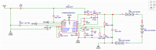
Here is the schematic

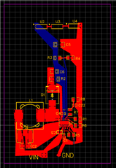
And here is the board layout

Again the help is greatly appreciated. Any changes if you could give an explanation as to why would also be greatly appreciated as I am trying to learn something new that I have never done before.

Appreciate you all!

-David

  • Our expert will give you reply next week.

  • Hi, David

    Could you pls kindly explain the problem you meet right now?

    There is no problem for your simulation circuit. And it is better if you could share the waveform of below pin, VOUT, SW, IOUT, VCC

  • Hello Zhiqian,

    I am not sure I had the simulation set correctly, as it was my first time using the software. The problem I am getting is no switching happening/ no boosting. On the physical circuit, SW pin wave is a solid line - some electrical noise, which tells me it is not switching for some reason. I think there may be something I don't understand as to why its not switching.

    I have a 10K pull up resistor on the fault pin, which I thought would be ideal to pull that to the 5V on the VCC pin when no faults are detected. When measuring on the real circuit, the voltage stays at 0V. Looking at a few other examples people have posted it seems maybe I should also have a pull up resistor on the ADIM & PWM, since I want 100% brightness 100% of the time with no dimming, and not just have them connected to the VCC pin. Those pins do both read 5V when powdered on.

    My main issue is the circuit is not switching, even though I believe it should be switching. Would it be possible for someone to double check my math based on the information I provided above with the Vin range, Vout range and Iout needed? I would greatly appreciate that if that could happen. It could be as simple as I have the LEDs hooked incorrectly and its reading LED short or something. I am not sure at this point. Any help is greatly appreciated.

    Thanks,

      David

  • Hi David,

    Our expert will give you feedback later.

  • Hi, David

    Could you pls give EN pin an external supply to try again?

    Where did you get this model for simulation?

  • Hello Zhiqian,

    When you say to give EN pin an external supply, you mean a different power supply and not just a pull up resistor to VCC correct? 

    The model was from EASYEDA in their simulation software. I am not sure that it is correct. Can you send me the pspice model and I will recreate the circuit there and test things out. Pspice model can be sent to this email is david@gilscustoms.com.

    I guess if adding a separate power supply to EN pin does work, is that common practice for this chip? It seems as though one would be able to just use the 5V from VCC to make it work, but again maybe I just don't understand it. Appreciate the help so far.

    -David

  • Hi David,

    Our expert will give you feedback later.

  • Hi, David

    We only have the simplis model for this device, I have sent you an email and pls check it.

    I am not sure if you get the correct model.

  • I will respond VIA email. I appreciate it!

  • Hello Zhiqian.

    Wondering if you were able to send the model. I haven't see it come through via email yet.

    Thanks,

      David

  • Hi, David

    Pls check it now.

  • Hello Zhiqian,

    It did come through this time. I appreciate it! I will give this a shot and see if I can figure out where my issue lies.

    Thank you!

  • Hi David,

    Our expert will give you feedback later.

  • I am also wondering if the reason my design is not working is because I don't have a PWM signal going to the PWM pin. I Thought you might be able to just give PWM and ADIM 5V but looking at the dimming mode configuration, I don't see an option that is label High and High for each pin.

    The model for simulation has been sent ove, though I am not sure how to use that, but I do see in there there is a signal generator setup for each pin which got me wondering if I do need a real PWM signal instead of just pulling them to 5V on the VCC pin.

    -David

  • Hi David,

    The expert will give you feedback later, thanks for the patience.

  • Hi, David

    Pls consider to use the model I sent you. We doesn't provide other model, so I have no ideas from that one.

    • The model was from EASYEDA in their simulation software
  • Hello Zhiqian,

    I have looked at the model, I am just unsure how TI has structured it/ what should be changed to fit my circuit.

    My question for the simulation is how do we use it. It appears there are 3 files, that work together. I would think the one labeled TOP_SYSTEM is where we should run the simulation after plugging in the values we have for our circuit. That schematic looks like this. 

    There is also the file called LP886x_EVM, which I would think is where I would plug in my values that I calculated for my circuit? Correct? I am also not sure how to do that since it seems there are default formulas that tie to other parts. Schematic looks like this

    Lastly there is the file called LED_Matrix. Which I would think is where you put values in for the LEDs being used/ how many and what not. Schematic looks like this

    Like I said the last two tie to the TOP_SYSTEM file, but it is not clear how to edit and use the simulation. Is there any guidance you can give on that or is there someone else that can chime in to help?

    My other question that came up was if the PWM pin needs a PWM signal or if that and ADIM can be pulled high? I am leaning towards no because of the chart for dimming modes but it is not clear if that is the case. Would love to mess around with the simulation, but again I have no idea how to set it up to get it to work. Any help there would be appreciated.

    Thanks,

      David

  • Hi David,

    The expert will give you feedback later, thanks for the patience.

  • Hi, David

    It is the total block of the system.

    The first one is a high level block. Another two are sub-block, one is for LED driver setup, you can change the value of the inductor or any other component. Another one is the LED setup, you can change it with different LED number and other setup.