Tool/software:
Hello.
I've designed schematics for a graduation assignment at university.
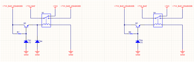
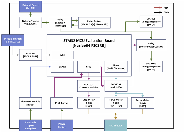
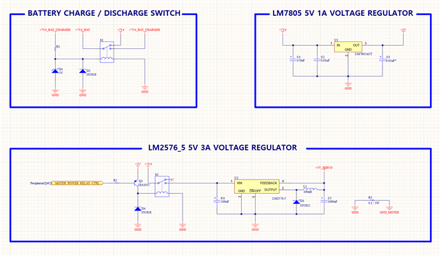
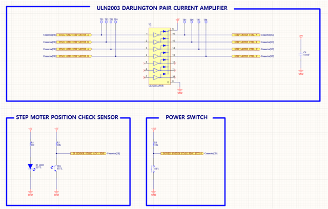
It used battery(Li-ion 18650 7.4[V]/ 2200[mAh]) and 3 moters and relay (coil voltage 5[V]) and etc. So, I designed a battery charge/discharge line using a relay. It has a voltage-divided circuit using resisters for operating the relay coil(7.4V -> 5V/ operating the relay coil voltage is 5[V]). But I forgot this design has issues with back electromotive force. So, I am thinking of changing this circuit to another. The circuit below is a question 1 circuit(operating relay coil). left is a zener circuit with a diode. and right is a zener circuit without diodes.
1. The operating relay coil has a back electromotive force. But I want to prevent this. Can I used zener diodes voltage regulated circuit? or using another diode to prevent back electromotive force.
2. I've used 3 motors. So I think voltage divided is safe(motor voltage and another process voltage). I used 2 different voltage regulators(LM7805 and LM2576-5/ make voltage is same 5[V]. and different maximum current LM7805 is 1[A] LM2576-5 is 3[A]). But I have no idea about the divided ground. Now just connected 0.1Ohms siment resister in between the ground and motor grounds. Is it ok? or can I use an OP-AMP voltage follower? or other safety methods?
Regards,
JIho.