Tool/software:
Hi
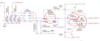
When OUT is low, is it possible to connect to the VEE voltage of -3.5V through PNP operation as below?
Can I connect to VEE, not source of FET?
Thanks
Tool/software:
Hi
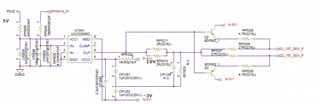
When OUT is low, is it possible to connect to the VEE voltage of -3.5V through PNP operation as below?
Can I connect to VEE, not source of FET?
Thanks