This thread has been locked.

If you have a related question, please click the "Ask a related question" button in the top right corner. The newly created question will be automatically linked to this question.

BQ40Z60: Qmax update not occurring

Part Number: BQ40Z60
Other Parts Discussed in Thread: BQ40Z50

Tool/software:

Hello everyone,

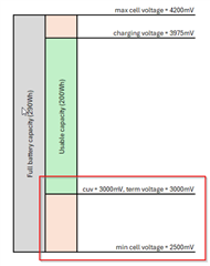
We are currently configuring a battery pack using the BQ40Z60. We have successfully completed the learning cycle using the same cells in our 160Wh battery pack. Now, we're making a new 200Wh battery pack with identical cells, but different voltage thresholds in order to achieve a different battery capacity.

During cycle testing however, we are unable to get Qmax updates. The cycle count increments (the pack is currently at 7 cycles), but Qmax cycle count remains at 0 and Qmax does not change.

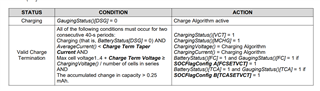
We've studied the Qmax update criteria from the datasheet and we don't think any of the four conditions apply. Can anyone help us out and tell us why Qmax updates are not occurring? I have attached the charge/discharge cycle logging and the device gg.csv files.

9999 200Wh 24-03-2025.gg.csv Log 9999 200Wh 24-03-2025.log

  • Hi Joep,

    Was there a learning cycle completed with the new pack using the different thresholds before this cycling? What thresholds were changed in this situation?

    Regards,

    Anthony

  • Hello Anthony,

    We haven't run a learning cycle using this pack as the cells are the same, only the voltage thresholds and capacities have changed.

    I have attached the file of the 160Wh pack, so you can compare the settings.

    2001 (2 cycles vol).gg.csv

  • Hi Joep,

    Please try running the learning cycle with the new pack, the gauge will calculate resistance and Qmax values independently for each cell, so the addition of a new cell could be causing this issue. 

    Regards,

    Anthony

  • Hello Anthony,

    We haven't added any new cells. In fact, no changes have been made to the hardware at all. Only a few voltage registers have been changed. Are you able to see from the logging what is keeping the Qmax update from occurring?

  • Hi Joep,

    I see that there have been changes to the design capacity values even though there has not been the addition to the cells. The design capacity should reflect the nominal capacity of the cells, not the amount of capacity that is wanted to be used. This will cause issues when the gauge is attempting to learn values such as Qmax. Once the learning cycle has been done, you can alter the amount of capacity intended to be used using the Reserve Capacity parameter.

    Regards,

    Anthony

  • Hello Anthony,

    The design capacity should reflect the nominal capacity of the cells, not the amount of capacity that is wanted to be used.

    SLUA903 "Achieving The Successful Learning Cycle", section 2.1 states otherwise:

    So what should I set the design capacity to then?

    Can you tell from the log files what the actual Qmax disqualification reason is?

  • Hi Joep,

    Please disregard this statement from this document, this document has not been maintained over time. Please ensure that the design capacity is the nominal capacity of the entire cell, and if you want to change the usable capacity to use the Reserve Capacity parameter. This will allow for the calculations to still be correct.

    Regards,

    Anthony

  • Hello Anthony,

    Can you point me to the latest version of this document, or a different document that properly explains the learning cycle and how to configure each register? I notice that SLUA903 is also referenced on the product page of the successor to this IC, the BQ40Z50. It seems strange to me that SLUA903 is no longer maintained for an older product, but a newer product still references this document.

    I would still like to know the actual Qmax update disqualification reason. According to the datasheets and whatever information I can piece together from various documents and forum posts, a different design capacity is not a Qmax update disqualification reason. How can I find the actual disqualification reason?

  • Hello Joep,

    This question is being reviewed and please allow for some addition time to review.

    Thank you,
    Alan

  • Hello Alan,

    Thank you for your time. Have you been able to review this issue yet? I would like to continue with configuring our new battery pack.

  • Hello Joep,

    There is no update version of the document and design capacity is the nominal capacity of the entire cell.

    Thank you,
    Alan

  • Hello Alan,

    We are using this document as guideline for the learning cycle. Does the document contain any more outdated information which we need to know about? Is there an errata document available?

  • Hi Joep,

    I believe that the rest of the configuration information from this document is ok to follow, along with the process instructions to complete the learning cycle. We do not have an errata document for this part.

    Regards,

    Anthony

  • Hello Anthony,

    So I tried limiting the usable capacity of my pack by using the reserve capacity parameter (as suggested by Anthony). I also changed the design capacity to the capacity of the full cell (instead of the desired usable capacity) and ran a few charge/discharge cycles after this, but Qmax still hasn't updated. I need some additional help in order to determine the proper register settings.

    I'm trying to achieve the following: I want to make a 4S6P battery pack. I want to limit the usable capacity of the pack in order to prevent excessive wear on the cells. In order to achieve this, the learning cycle document tells me to adjust the charge voltage and termination voltages in order to limit the capacity to the desired amount.

    These values have been determined by logging the voltage of the cell during constant current discharge, which gives me the voltages at which the desired battery capacity is available (max voltage = 3975mV, min voltage = 3000mV).

    I want the battery pack to be able to shut itself down when the previously determined minimum voltage is reached (NOT when the minimum cell voltage from the cell datasheet is reached, which is 2500mV). Therefore, the cell undervoltage has been set to 3000mV.

    The total pack capacity according to the manufacturer datasheet should be 290Wh. The actual usable capacity by the battery user needs to be 200Wh.

    The following image illustrates the above situation:

    However, the Reserve capacity register is defined as the capacity between the term voltage and the absolute minimum cell voltage according to the datasheet:

    Because the cell undervoltage and term voltage are set to the same value, the reserve capacity register isn't going to fix the Qmax problem I'm facing.

    How would I go about determining the proper values of the mentioned registers to have the battery pack behave as in the picture *and* have it shut itself down using the two back-to-back MOSFETs?

  • Hello Joep,

    This question is being reviewed and please allow for some addition time to review.

    Thank you,
    Alan

  • Hi Joep,

    Sorry for the delay, what you are looking to do here is achievable. As discussed prior, the most important factor is that the learning cycle is done for the full 290Wh capacity of this cell, then modifications can be done afterwards.

    For the gauge to recognize 100% at 3975mV instead of 4200mV, it will just need the Valid Charge Termination conditions to be met at 3975mV instead of 4200mV. This will lead to the gauge taking a DOD at EOC point at this voltage where it will then qualify it as the end of charge point. The conditions for VCT are in section 4.7 of the TRM seen below:

    The most important part of this is configuring the Advanced Charging Algorithm to have ChargingVoltage() at this point reflect 3975mV, instead of 4200mV.

    For the bottom region, I believe this configuration will work for the intended function. The Term Voltage details when the device will recognize 0% SOC, and if you would like the DSG FET to turn off due to the protection being triggered at this time, then you can place the CUV here as well. Please ensure that the recovery thresholds are set correctly at this time as well.

    Regards,

    Anthony

  • Hi Anthony,

    Thank you for your in-depth reply. So if I understand correctly, we should set design capacity to 290Wh and do a learning cycle with the cell and charge voltages set to 4200mV and 2500mV. Afterwards, we make the modifications to the cell and charge voltages.

    What should reserve capacity be set to? Should it be set to the sum of both red areas (90Wh), or only the bottom red area?

  • Hi Joep,

    I believe this should only be set to the bottom red area.

    Regards,

    Anthony

  • Hello Anthony,

    We have tested the settings as you described above. In order to make sure we're starting from a clean slate, we started a new learning cycle using the default image from the BQ40Z60 website. We made the necessary modifications regarding cell voltage, capacity and device settings as described in the learning cycle documentation.

    After completing the learning cycle, we've adjusted the cell voltages and remaining capacity to match the image we've discussed previously. The reserve capacity was determined by analyzing the discharge logging between 3V and 2,5V. Unlike the previous attempt, the design capacity was set to the full cell capacity.

    Qmax update now seems to work as expected. After the learning cycle, the update status is 0x0E.

    The state of health, however, is now only 73% after the first charge/discharge cycle. I would expect the SoH to be 100%, since there has been no degradation yet. How do we fix this?

    I have attached the logging of the last charge/discharge cycle where the drop in SoH can be seen. I have also attached the device settings.

    77013.settings.gg.csv

    logging.log

  • Hello Anthony,

    Have you been able to look at our latest log file and settings yet?

  • Hi Joep,

    Sorry for the delay, it seems like the SOH Load Rate parameter does not match the discharge that is occurring. Can you please try changing this from 5 to 6.7 and see if the performance improves?

    Regards,

    Anthony

  • Hello Anthony,

    We have changed the SoH load rate parameter from 5 to 6,7 but the SoH is still 73% after a charge/discharge cycle. You’ll find the log file and settings below.

    According to the datasheet, the state of health is calculated by dividing the load rate compensated full charge capacity (SoH FCC) by the design capacity. Because you told us to set the design capacity to the full cell capacity according to the cell manufacturer instead of the usable capacity, the SoH will never be better than 73%.

    Does this mean that design capacity should have been set to the usable capacity instead?

     load rate.logload rate.gg.csv

  • Hi Joep,

    Thanks for the information, I understand now. Since the amount of passed charge currently is much lower than the design capacity, this is bringing down the FCC in turn with the SOH. Please allow me to consult our team and get back to you regarding a solution.

    Regards,

    Anthny

  • Hello Anthony,

    Have you been able to consult with your team regarding a solution yet?

  • Hello Joep,

    We have received your update and we are working on your response.

    Thank you,
    Alan

  • Hello Alan,

    I understand the issue might be difficult to solve. Could you give me an ETA for a solution? We need to finish configuring the battery packs for our customer.

  • Hi Joep,

    I was able to consult our team regarding this issue, where they believe that the design capacity should not be changed in this situation to fit the FCC value. The gauge is heavily reliant on this value within the gauging algorithm, where any parameter or calculation that references a specific capacity rate is referencing this value.

    We believe the best way to move forward with this issue is to have the host scale the value, where the 73% SOH will be reflected as 100%. 

    Regards,

    Anthony

  • Hello Anthony,

    Unfortunately fixing this issue on the host side is not possible for all our products, since the host is implemented in multiple different products at different customers. Updating the host software for every customer and product is not feasible. This means that existing batteries will be incompatible with new hosts.

    Is there another way to setup the IC to achieve the functionality that we need?