This thread has been locked.

If you have a related question, please click the "Ask a related question" button in the top right corner. The newly created question will be automatically linked to this question.

UCC28950: Lshim Temperature rise Issue

Part Number: UCC28950

Tool/software:

Hi,

We are working on UCC28950 with below specifications of the power supply:

Input: 700V,

Output: 48V, 5A

Fsw: 50kHz

As per calculations from SLUC222D and slua560d, the Shim inductor RMS current is 1A.

We tried multiple Inductors ranging as follows:

1. Inductor 1: 470uH, DCR 0.278ohms, SRF 2.3MHz, Isat 1.5A, Irms 1.2A

2. Inductor 2: 470uH, DCR 0.20ohms, SRF 1.35MHz, Isat 2.4A, Irsm 1.39A

3. Inductor 3: 470uH, DCR 0.0873ohms, SRF 1.7MHz, Isat 3.2A, Irms 5.5A

4. Inductor 4: 470uH, DCR 0.187ohms, SRF Not mentioned,Idc 4A.

The inductors 1,2 and 3 are showing temperature rise of 110C at room temperature at full load.

Inductor 4 is showing 70C temperature rise.

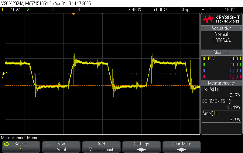
We are not sure what is causing this issue, after measurement of the current passing through Inductor, the rms current comes around 1A, pk-pk current is 3.8A.

Attached is the waveform of the current passing through the Inductor, measured using CT of 1:100 ratio with 150Ohm load on secondary.

I hope that is helpful.

Please can you guide us how to derive Lshim inductor parameters apart from calculations shown in SLUC222D and slua560d to achieve minimal temperature rise.

Thank you,

Regards

Gaurang

  • Hello,


    Your inquiry has been received and it will be reviewed in the order it was received.


    Regards,

  • Hi,

    Also, please note that the diodes at primary winding of the transformer are damaging (D5 and D11 location in slua560d) in our design, below are the observations and diode part number.

    Diode part number: STTH512B-TR

    Observation 1: At full load of 5A 48V, diodes are working ok.

    Observation 1: At light load of 1A 48V, diodes damaged hence Primary side mosfets also got damaged.

    Please can we have some better calculations or methodology to choose these diodes.

    Let me know if you need more details of the design.

  • Hi,

    Also, please note that the diodes at primary winding of the transformer are damaging (D5 and D11 location in slua560d) in our design, below are the observations and diode part number.

    Diode part number: STTH512B-TR

    Observation 1: At full load of 5A 48V, diodes are working ok.

    Observation 1: At light load of 1A 48V, diodes damaged hence Primary side mosfets also got damaged.

    Please can we have some better calculations or methodology to choose these diodes.

    Let me know if you need more details of the design.

  • Hello,


    Your inquiry has been received and will be answered in the order it was received.


    Regards,

  • Hello,


    When it comes to the clamping diodes, I would not think that at lighter loads these would not get damaged.

    I am wondering if you are forcing a reverse current through the transformer because you are not turning off the SR FETs to prevent reverse current from going through them.  Make sure you use the DCM comparator to turn off the SR FETs before critical conduction.  Application note slua560d.

    If your maximum DCR is 0.278 and your RMS current is A the conduction losses would be 278 mW.  I would not think that would cause the inductor to reach 110 C.  It sounds like your inductors might be saturating. 


    I reviewed your current waveform for the current going through the inductor and it looks like your design is operating near 77% duty cycle.  This current should like what is represented in figure 4-1 of the application note.   I am not seeing any evidence of inductor ripple current in your waveform.  So, the CT you are using to look at this current is not measuring it correctly or there is something wrong in your design.  You might want to check your schematic vs the application note.

    You might want to check your CS waveform to make sure the current sense signal looks correct.  If it does not you might be saturating your current sense transformer.


    The application note uses peak current mode control.  When done correctly it will prevent transformer saturation.  If you are not using peak current mode control, I would suggest you switch to that as well.  Otherwise you will need a DC blocking capacitor in series with the transformer input.


    Regards,


  • Hi Mike,

    I appreciate your response and analysis, I will look further into DCM for Output Fets.

    About the comment "This current should like what is represented in figure 4-1 of the application note.", figure 4-1 shows Primary current, Output fet currents and Output inductor currents, correct me if I am wrong, do you mean that Shim Inductor current will be same as Primary current? I was in the impression that shim current will differ with the current passing through Transformer primary.

    Note that the CT we used to measure the current passing through Lshim and the CT used as Primary current sensing in our design are same and the part number is PE-51687NL, this CT is having same parameters as PE-63587NL used in slua560d.

  • Hello,


    Please see my comments below.

    I appreciate your response and analysis, I will look further into DCM for Output Fets.

    About the comment "This current should like what is represented in figure 4-1 of the application note.", figure 4-1 shows Primary current, Output fet currents and Output inductor currents, correct me if I am wrong, do you mean that Shim Inductor current will be same as Primary current?

    Yes

    I was in the impression that shim current will differ with the current passing through Transformer primary.

    The current should be roughly the same.  The issue is when you out of freewheeling with reverse current going through the transformer.  That is what the diodes are for.


    Note that the CT we used to measure the current passing through Lshim and the CT used as Primary current sensing in our design are same and the part number is PE-51687NL, this CT is having same parameters as PE-63587NL used in slua560d.

    Thanks for letting me know.  The current still does not look correct.  I would use a current probe to verify this is truly what the current looks like.


    Regards,