This thread has been locked.

If you have a related question, please click the "Ask a related question" button in the top right corner. The newly created question will be automatically linked to this question.

TLA431: parameter Minimum cathode current for regulation

Part Number: TLA431
Other Parts Discussed in Thread: TL431

Tool/software:

Good afternoon,

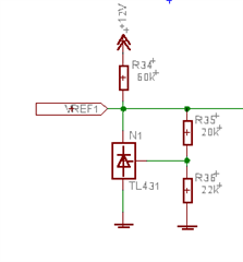
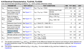
According to the datasheet, the maximum value of the parameter Minimum cathode current for regulation is 200uA. But if I have the connection as shown in the picture, the regulation on the TLA431 starts working only from a current of approx. 650uA (R34 18k). Where am I making a mistake?

Thank you for the answer
Karel

  • Hi Karel,

    Thanks for your question!

    I see that in the diagram you are using the TL431 and not the TLA431. Are you seeing the 650uA behavior on a physical board, or via this simulation?

    Depending on which TL431 device is used, Ika_min behavior is consistent with the datasheet. For example, please see the Ika_min for the TL431AI device below:

    I hope this helps!

    Best Regards,

    Andrew Li

  • Hi Andrew,

    I'm testing this on a real board, where I have a TLA431AIDBZR connected. (bought on Mouser) That's why it doesn't match the datasheet. I need to know if in this connection (see previous picture) when using a TLA431AIDBZR, the regulation should work even at IKA above 200uA.
    Thank you for the answer.

  • Hi Karel,

    Thanks for the update!

    The IKA_min (max) specification should hold for any situation.

    For further support,

    1. Is there any connected load?

    2. Is this happening for multiple devices or just one?

    3. Is the device behaving this way across multiple boards?

    Best Regards,

    Andrew Li

  • Hi Andrew,

    For now, I'm just testing this connection, so it's been tested on one board and one TLA431. I'm using the voltage from the TLA431 as a reference on two inputs of the comparator, see fig.

    BR

    Karel

  • Hi Karel,

    Could you please let me know which comparators you are using? 

    Also, does this behavior continue if you disconnect the load?

    Please let me know if you could provide this information or some scope shots which can help in the debugging process.

    Best Regards,

    Andrew Li

  • Hi Andrew,

    -I am using a comparator LP2901DR
    -Yes, the problem is before the load is connected.

    BR

    Karel

  • Hi Karel,

    Let me double check with the team and get back to you tomorrow.

    Best Regards,

    Andrew Li

  • Please note that the current-limiting resistor for a shunt regulator must be sized for the maximum load.

    An additional current of about 113 µA flows through the R35/R36 divider. You have not shown what is connected to VREF1, but if there is a divider like with VREF3, then an additional 184 µA flows through it.

    The current through R34 is (12 V − 4.76 V) / 60 kΩ ≈ 120 µA, which is not enough for the TLA431 alone even without the additional loads.

    R34 = 18 kΩ results in about 402 µA, which sounds OK if there is a divider connected to VREF1. Considering the component tolerances and adding a safety factor, I would just use R34 = 10 kΩ.

  • Hi Karel,

    Thanks for your patience!

    Please consider the total current required by the load and into the reference pin during this calculation as this can have an effect for minimum current requirements.

    One way to test this could also be to use an ammeter to determine how much current is being shunted into the cathode of the device (measure Ika) to see if it is above the 0.2mA requirement.

    I hope this helps!

    Best Regards,

    Andrew Li