This thread has been locked.

If you have a related question, please click the "Ask a related question" button in the top right corner. The newly created question will be automatically linked to this question.

LMR43620-Q1: PFM operation resulting in strange behavior

Part Number: LMR43620-Q1

Tool/software:

Hello,

On my design I used several LMR43620RS3QRPERQ1 converters which are using PFM (Pulse Frequency Mode) in light load conditions.

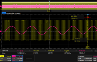
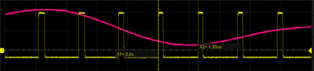
For a 3V3 converters, the behavior is understandable with that kind of decoupling (don't bother about the red curve) with no load and with load :

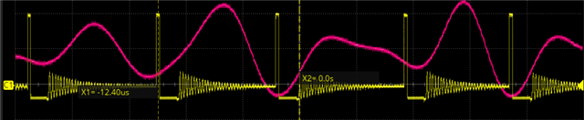
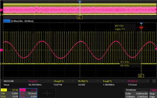
However, my 6V converter is presenting that kind of decoupling with nominal load (estimated at 250mA) and with +500mA load :

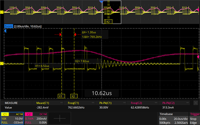
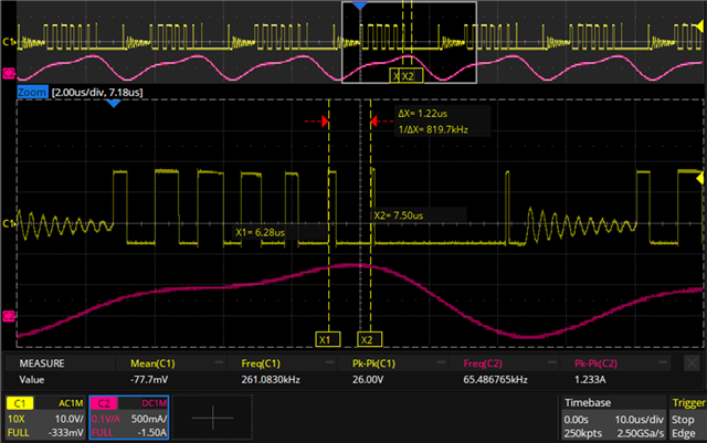
Unfortunately for me, it results in a high input current ripple because of a filtering resonance at 60kHz.

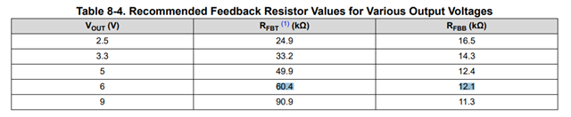
Would it be solved with a FPWM version of the component ? Could it be related to the feedback resistor not respecting the 10kohms parallel recommendation ?

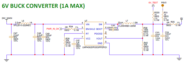
My schematic looks like this :

Best regards,

Alexian

  • Hi Alexian,

    Could you try using the 6Vout value recommended in the table? 

    What is the sw freq? The inductor value looks a little large

    Regards,

    Rahil

  • Hello,

    I tried with others feedback resistor values, it changed a little bit the shape but not much (did not have the recommended values, tried with 56k and 11k resulting in 6.08V).

    After gathering informations concerning Pulse Frequency Mode, it seems that the behavior that I observe is more common than I thought. My input ripple current is amplified by the resonance of my input filter : removing my input inductors reduced it significantly.

    However, I still don't understand why in some conditions, the converter switches several times before opening both MOSFETs and sometimes it occures after every switch like on the first curve shown. Even more disturbing, I don't understand why it keeps operating in that mode even with a bigger load (last curve shown).

    My switching frequency is at 790kHz. I will change the reference to get one with the MODE pin and force it into FPWM mode as I don't really need to optimise the power consumption is light load situations.

    Best regards,

    Alexian

  • Hi Alexian,

    Sounds like using force FPWM mode will solve this problem. Let me know if any other problems arise.

    Regards,

    Rahil

  • Hello,

    I changed the component reference and forced the Fixed PWM mode, and unfortunately, the current ripple is still here !

    Something strange is also present : a frequency modulation on the buck switching :

    Here is another buck acting normal with the same configuration :

    It seems like an instability on this buck converter, but I don't know how to fix it...

    Already tried to increase input capacitor with different values (47uF, 150uF, 680uF).

    On the output of this converter, there are only 2 LDO converters 6V to 5V, no directly powered components.

  • Can you try to isolate the buck and use an e-load?

    Regards,

    Rahil