This thread has been locked.

If you have a related question, please click the "Ask a related question" button in the top right corner. The newly created question will be automatically linked to this question.

TPS40210: Application issues.

Expert 2180 points

Part Number: TPS40210

Tool/software:

Hi Team,

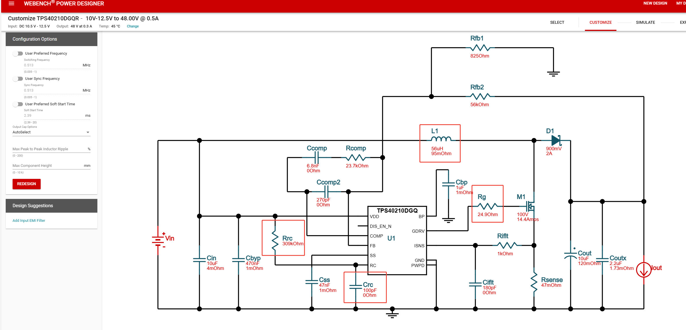
We are using TPS40210 chip to design BOOST circuit, 12V to 48V, with a designed output power of about 15W, for non-standard POC power supply. The circuit diagram is attached.

1. Fault phenomenon: The factory aged the machine in a 45 ℃ environment and found that the POC was not supplying power. After positioning, it was found that the switch MOS (Q2 AM4392N) was damaged and the D-S was short circuited;
2. Fault analysis:
a. Q2 MOS has been analyzed by the supplier and it has been confirmed that the interior has been burnt out with no obvious marks on the surface;
b, Our experimental data shows that there may be a significant relationship with R15, which has recently been changed to 5mR with a failure rate of approximately 10% to 15%; Before the change, R15=10mR, The failure rate is about 1% to 2%; But both were burnt out in Q2.
c, During normal operation, the surface temperature of Q2 MOS was tested at 82.5 ℃ (Ta=45 ℃).
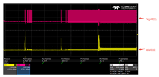
d, During normal operation, the waveforms of Vgs and Ids were measured, as shown in the attached image, and no abnormalities were observed.
e, We replaced Q2 with a higher current one, LTS20N15SQ, 4.7A. Q2 also burned out, with a failure rate of 10%~15% (R15=5mR at this time).

This issue has been bothering us for some time. Please help analyze it urgently. If you need to provide other information, please let us know.

Thank you!

DS_AM4392N_1A.pdfLTS20N15SQ-V4.0.pdf

  • Hi Reed,

    Thanks for using the e2e forums and giving a detailed description.
    I am not a full expert for MOSFET, but the most typical root causes for damage are overvoltage or heat.
    As both FETs are rated for 150V and there are no overshoots on the switch node pin, overvoltage is very unlikely.
    Layout is also important when it comes to temperature related issues.

    What caught my eye is the use of a 24.9 Ohm gate resistor (R10).
    We commonly do not recommend gate resistance above 10 Ohm as the slopes may get very slow and switching losses increase.
    Here also the switching frequency has an effect, as it defines how often the switch operates.

    To reduce stress on the MOSFET, they can try to reduce the switching frequency and reduce the R10 resistance.

    Best regards,
    Niklas

  • Hi Niklas,

    1. Is there a relationship between the R15 resistor and the damage to this MOS during normal operation?
    2. Yesterday, there was a test where a normal board was heated in the vicinity of the MOS using a 170 temperature soldering air gun in working condition for 5 minutes without any damage.

    The current reference design is as follows.

  • Hi Reed,

    1. This is possible. R15 defines when the device activates the overcurrent protection. If OCP is triggered, the device will stop operation and reset, so there is no switching during the reset time and the MOSFET stays open.
    If a smaller sense resistor is chosen, the device keeps operation even with higher current values.
    The question then would be, if OCP is triggered or not in the given conditions.

    2. This webench design seems to use a larger inductance of 56uH instead of 22uH, which reduces the current ripple and peak inductor current.
    Did you also use a different MOSFET device for this application, or was it the same as on the previous board?

    Best regards,
    Niklas

  • Hi Niklas,

    1. Under given conditions, the OCP is not triggered, and the MOSFET Ids current is approximately 1.25A. We are concerned that R15 might be too small, which could cause instability in the TPS40210 chip's operation, leading to chip failure and subsequent MOSFET damage?

    2. In the above test phase, the MOSFET was not replaced.

  • Hi Bright,

    Thanks for the additional comments.
    I agree that if the sense resistor is too small and there is only a very flat current slope measured at the sense resistor, the system can become unstable.
    We recommend to dimension the resistor such that it does not trigger OCP during operation with max load.
    A 5mOhm resistor sets the limit to 30A. If the peak load is merely 500mA, this is way too large and also exceed the saturation current limit of the inductor.
    With 47mOhm, the limit is set to 3.2A, which is a more suitable selection.

    Best regards,
    Niklas