Other Parts Discussed in Thread: BQ25185, TPS63020
Tool/software:
Hi guys,
I've been working on a gateway that should work based on solar panel recharging.
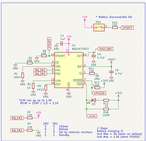
I've been switching between different IC's and my latest design is with the BQ24075. I wasn't able to fully tested it yet, but so far it seems to work ok. I plan to do deep cycles this week but so far the schematic looks something like this:
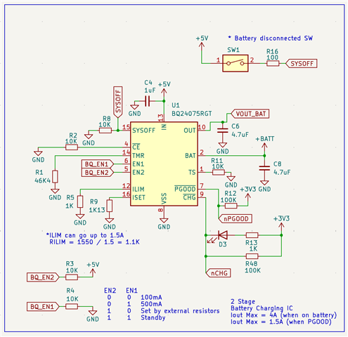
I'm using the AP63205WU buck to regulate the input voltage from the solar panel to 5V and then sourcing it to the BQ24075. I've noticed already that probably instead of connecting BQ_EN2 to +5V I should have connected it instead to VOUT_BAT. But besides of that, anything else that pop's out?
nCHG is going low level even without the battery connected. However, activating SYSOFF by swathing SW1 makes it high level again. Is this the expected behavior? I'm bypassing BAT pin with a 4.7uF capacitor.
One last question, the BQ24075 will not protect the battery right? I still need to use a OVP and UVP IC right?
Thanks in advance,
Best regards,
Fernando Fontes