This thread has been locked.

If you have a related question, please click the "Ask a related question" button in the top right corner. The newly created question will be automatically linked to this question.

LM3409: LM3409 only giving correct PWM output upto 50% duty cycle

Part Number: LM3409

Tool/software:

Hi team,

We have designed the below mentioned LED current driver project with LM3409 as the main component. 

Here's the issue

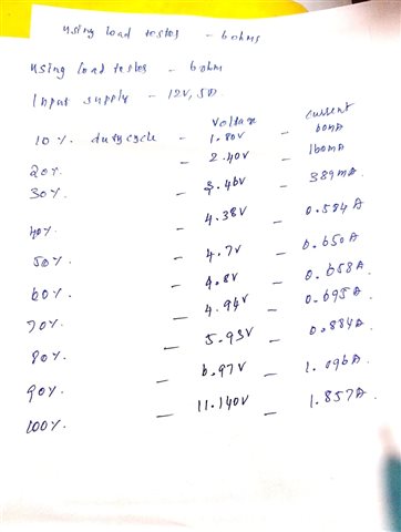
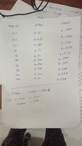
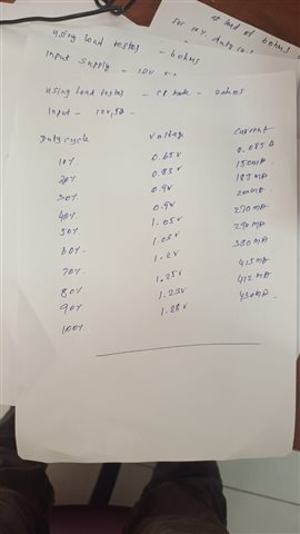
- The current is being controlled properly upto any duty cycle percentage below 50% (i.e., if i provide 25, 26 etc., percentages the current is controlled fine) however the moment we give any duty cycle beyond 50% it looks like the IC is either shutting down, we see no reading on our electronic load.

I can provide you more waveforms or probe data if you tell me which place to probe in the schematic.

  • Can you share the waveform of

    1. SW node, inductor current , COFF, PWM in one figure with 5uS/div and 1mS/div ( may adjust it due to dimming frequency)  

    2. PGATE, inductor current , COFF, PWM  in one figure with 5uS/div and 1mS/div ( may adjust it due to dimming frequency)  

  • @xiaoguang

    We are unable to capture all the waveforms at the moment due to issues with our oscilloscopes, until we fix that we have taken the current ratings for various PWM duty cycles. Do you see any issues ?

    Electronic load tester is used at 6ohms resistance mode

    12V is the input voltage, let me know if you see any issues.

  • I would suggest monitoring the waveforms with oscilloscoper.

    The current is set to over 3A, with 6 ohm load, the device will run into dropout mode that output voltage charged up to input voltage.

  • Hi, thanks for the reply. Can you please suggest me what should the electronic load setting be?? I mean what should the resistance setting should be for the testing purpose?

  • With 3A 6oHm, Vout = 3*6=18V, which is over 12V input. The device won't deliver the target current as expected. 

    You may use LED or constant voltage output or lower load resistor value to < 3ohm etc. 

    If you can monitor waveform with oscilloscope, then you can better understand the operation condition.  

  • Hi, I think there's a confusion here. Our power supply is just set to provide 3A current thats it, we're not providing the entire current right? To be more clear, we have a bench power supply on which we have set the voltage to 12V and current max to 3A and when we switch on the power supply only draws as much current as needed only right?? 

    So I didn't understand your suggestion about 3*6=18V. can you please clarify this sir?

  • LM3409 is constant current led driver. In your schematic, R11= 75mohm, targeted inductor peak current is around 246mV/75mohm = 3.2A, average current around 3A. 

    You might go through LM3409 datasheet as well as Typical Applications in the datasheet. 

  • targeted inductor peak current

    Doesn't this mean that the max current the driver will support is 3A right? But when we use PWM isn't this current regulated automatically so therefore the voltage should also come down?

    I may be understanding something very fundamental wrongly. 

  • Please refer to datasheet about PWM dimming using the EN pin 

    If you want to reduce DC current, you can trim IADJ as analog dimming. Refer to 8.3.2.1 Adjustable Peak Current Control

  • We have tested with some extra load values less than 3 ohms and looks like the values are still odd. Can you check please?


    Constant resistance 1 ohm as load


    Constant resistance 2 ohm as load

    We are planning to connect a couple of LED's to the board and see if the circuit works. Do you think as per the existing circuit diagram I shared earlier the circuit is safe to be connected with LED's? What is the typical setup TI uses to validate current drivers like this using electronic load testers?

    Thanks

  • Would you pls kindly use oscilloscoper to capture waveforms? For example,  VIN, VOUT, COFF, switch node voltage, and inductor current?