This thread has been locked.

If you have a related question, please click the "Ask a related question" button in the top right corner. The newly created question will be automatically linked to this question.

REF3425: Layout review

Part Number: REF3425

Tool/software:

Hello TI team,

We are using some TI ICs in power section of our design. The Designator and its part numbers are as below,

1. U20: REF3425IDBVR

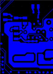
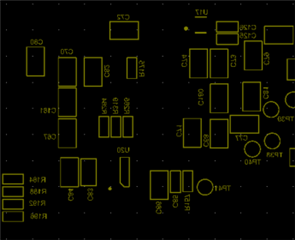
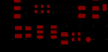
As we have completed the layout we would like to review it from TI team. I am attaching the schematic sheets PDF containing the IC listed above. I am also attaching the Gerber document for review.

Please review attached files and let us know if any changes are required.

Regards,

Nitesh

2110.TI power.pdf7801.Gerber Output.rar

  • Hi Nitesh,

    I see no issue with the schematic. I looked through the gerber files, but I had a hard time locating REF3425IDBVR. I could see U20 in the .GBO file, but I couldn't find the corresponding pads for the layout for the bottom layer in the .GBL file. 

    Mainly, I'm looking to see where you have connected OUT_F and OUT_S. In general, best practice is to connect those pins as close to the ADC as possible. This is also described  in section 10.2.2.2 of the datasheet. 

    Thanks,

    Jackson