Tool/software:
Hello TI team,
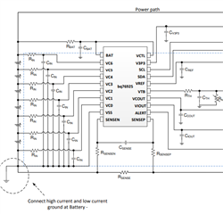
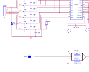
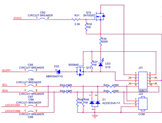
I'm working on a custom battery management design using SLUA707 ("3 to 6 Cells Battery-Management System Based On bq76925 + MSP430G2xx2") as a reference. While reviewing the schematics in the application note, I noticed that various components labeled as CB1, CB2, ..., CB10 etc. are marked as "CIRCUIT BREAKER" but are not described further in the documentation.
Could you please clarify:
-
What function these CBx elements serve in the reference design?
-
Are they placeholders for physical circuit breakers or symbolic representations for test/debug points( if so can i use 0 ohm resistors in place)?
-
Are there recommended part numbers or implementation guidelines for these circuit breakers for protection or system isolation purposes?
-
Should I include these CB components in my own design, and if so, under what use-case conditions?
Understanding the role and selection criteria of these CBx components will help me design a safer and more robust BMS system.
Thanks in advance for your support!
Best regards,
Prashant Singh