This thread has been locked.

If you have a related question, please click the "Ask a related question" button in the top right corner. The newly created question will be automatically linked to this question.

TPS7A4701EVM-094: Test Set-Up

Part Number: TPS7A4701EVM-094

Tool/software:

Hi,

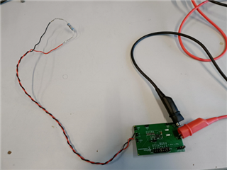
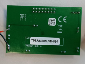
I require assistance in setting up a test set-up for the EVM. I am using Rigol Electronic load to check for the current output.
When I connect Vout and Gnd of the EVM to the Rigol load and set it in Continuous current mode at 10mA. Before turning the load on I am getting the desired output voltage but when I turn on the load the voltage drops to 0.
What might be the issue behind this?

I am using the device in Any out mode where I have shorted J8 connector and set the configuration to get 3.3V output. Please let me know the right set-up so that I would be able to get the output of at least 700mA.

Thanks & Regards 
Sudhir D 

  • Hi Sudhir,

    I suspect this may be caused by the electronic load's current loop overshooting when it turns on, causing the LDO to enter overcurrent protection. If possible, can you place a 330Ω resistor across the EVM output and confirm that the LDO functions as expected? That'd help rule out the LDO or EVM as the source of the issue. 

    If the EVM works as expected with a resistive load, there are a few tests to try: 

    1. Double check your load's firmware is up to date. My own DL3031A had a significant overshoot issue (load steps from 0-3A would hit 10A of overshoot, for example) during turn-on that was fixed by updating to the most recent firmware. 

    2. Use the low-current range on the load (if you aren't already)

    3. Turn the load's slew rate down to the lowest setting you can (if you haven't already)

    4. Try setting the output current on the load to the minimum setpoint you can, then manually increasing it in small increments to reach 10mA. This can help compensate for the firmware overshoot issue if a firmware update isn't possible. 

    Best Regards,

    Alex Davis

  • Hi Alex,

    I placed the 330Ω resistor across the output connectors J3 and J4 of the EVM and supplied the input voltage of 30V. Again, I faced the same issue. The voltage across the resistor was 0.197V when probed using a Multimeter. When I remove the resistor, I get the 3.3V when checked using the Multimeter. 

    I have attached the picture showing the connections which I have made. 


    Please let me know how to proceed.

    Thanks & Regards
    Sudhir D 

  • Hi Sudhir,

    Can you confirm the input voltage to the EVM is correct when the load is applied? 

    Best Regards,

    Alex Davis

  • Hi Alex,

    I am using Rigol DP2031 to power the Board. I have set the Voltage limit at 30V and current limit at 1A.
    I probed the input voltage using a Multimeter when the load is connected as above and was able to observe 30V at connector J1, C1 pad 1, C2 pad 1 and at the pads connecting to pins 15&16 of the LDO. Again, when the voltage across the load is probed, I am getting 0.195V. But under no-load condition I am getting the 3.3V output. 

    One other thing I am noticing is that when under No-Load the amount of current drawn is 0.813mA and when the Load is connected the current drawn is 1.3mA. 

    Let me know how to proceed.

    Thanks & Regards
    Sudhir D

  • Hi Sudhir,

    The 0.813mA quiescent current is pretty close to the datasheet value for the ground pin current. I don't see any issues with your test setup, so the next thing to try would be to swap a new TPS7A4701 device onto the EVM (or try a new EVM) to rule out device damage. 

    Best Regards,

    Alex Davis

  • Hi Alex,

    I will give an update once I get the IC and replace it on the EVM.

    Thanks & Regards
    Sudhir D