This thread has been locked.

If you have a related question, please click the "Ask a related question" button in the top right corner. The newly created question will be automatically linked to this question.

BQ25756E: VIN input generates oscillations

Part Number: BQ25756E
Other Parts Discussed in Thread: EV2400

Tool/software:

Hello TI team,

I have recently used your BQ25756E for charger PCB design, my circuit and PCB are attached. I tested it under pure resistor programming condition, DRV_SUP is powered by REGN and the load is CV load. Currently I encountered the following problem I hope to get your help:

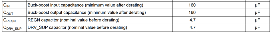
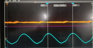
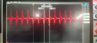
When I input a DC voltage with VIN of 6V and maximum 2A, VIN will generate intermittent oscillations (70Hz) causing the chip not to work properly, as shown in the red waveform below, I soldered a 4.7uF and 150uF capacitor on the input side and a 150uF capacitor on the output side at the moment. Is this problem caused by my capacitors being too small and how to fix it?

PS: When I use a power supply with less output power to input a DC current with a VIN of 5V and a maximum of 0.3A the chip shows normal operation with no large fluctuations in VIN.BQ25756E.rar

Thanks in advance!

  • Hi,

    The minimum input and output capacitance per datasheet is shown below:

    If you can read the I2C status and fault registers using your own MCU or the EV2400 software, we can confirm that the capacitance is the problem.

    Regards,

    Jeff 

  • Hello,

    Thanks for your reply!

    I re-tested today and found that it was a problem with my test condition setting, I set the charging cutoff voltage for the chip to 16.8V, but I previously set the CV load to less than 10V, when I set the CV to 16.8V the chip was able to work properly, now I have the following questions:

    1. Is my above test CV load voltage setting correct?

    2. My current output voltage still has a spurious waveform around 5V as shown below(red waveform). How can I reduce these fluctuations to get a more stable DC voltage output?

    Thanks in advance!

  • Hi,

    Do the status and fault report any fault conditions?  If not, then you try disabling PFM mode.  PFM off results in the lowest output ripple.

    Regards,

    Jeff

  • Hello,

    Thanks for your reply!

    Do the status and fault report any fault conditions?

    My EV2400 has broken,so I can't read I2C data,but the LED status is correct,the LED connected to STAT1 and PG is on during the test.

    If not, then you try disabling PFM mode.  PFM off results in the lowest output ripple.

    My chip is now operating in pure resistor programming by default, will this case turn on PFM mode?

    Thanks in advance!

  • Hi,

    Some "faults" like IINDPM or VINDPM do not result in STAT blinking.  PFM is default on.  Does the ripple voltage reduce as the load increases?  At higher load, the charger exits PFM and enters PWM.

    Regards,

    Jeff

  • Hello,

    Thanks for your reply!

    Does the ripple voltage reduce as the load increases? 

    I currently set the charging cutoff voltage to 16.8V,charging current to 1A.Currently the output constant voltage load is set to 16.8V,but when I try to increase the input voltage (10V 12V 19V 21V) I find that the system stabilizes the operation with a relatively small current (<1A) resulting in my overall operating power of 15W.How can I increase the load in the CV test?

    How can I reduce these fluctuations to get a more stable DC voltage output?

    Regarding this issue, I found that the main reason for the fluctuation is the CV load setting issue, because I set the charging cutoff voltage to 16.8V, when I increase the CV value from 8V to 16.8V the voltage fluctuation will be reduced accordingly, at present I observe that the corresponding MOS gate operating waveforms under the buck and boost modes are normal in the PFM mode, and the transfer efficiency is around 90%. Is this voltage fluctuation normal during CV test?

    Thanks in advance!

  • HI,

    Are you using an electronic load in constant voltage to simulate a battery?  

    Regards,

    Jeff

  • Hello,

    Thanks for your reply!

    Are you using an electronic load in constant voltage to simulate a battery? 

    Yes,as of now I have been using the constant voltage gear of the electronic load to simulate the battery and thus the Fast charge CC process. However, I have found that the system does not reach the set ICHG charging current value when operating at steady state when using this load. My current ICHG setting is 1A, but when I input a DC voltage of 9V, the circuit works stably at 9V,1.71A input and 16.8V,0.86A output, can I increase the load by increasing the ICHG value?

    Besides,I wanna konw if the following case is normal during CV load test? 

    Regarding this issue, I found that the main reason for the fluctuation is the CV load setting issue, because I set the charging cutoff voltage to 16.8V, when I increase the CV value from 8V to 16.8V the voltage fluctuation will be reduced accordingly, at present I observe that the corresponding MOS gate operating waveforms under the buck and boost modes are normal in the PFM mode, and the transfer efficiency is around 90%. Is this voltage fluctuation normal during CV test?

    Thanks in advance!

  • Hi,

    I recommend adding a big capacitor (>100uF) in parallel with the eload, connected close to BAT pin.  An eload + leads connecting to it are highly resistive.  This increases the ripple.  I don't expect as much ripple as you are seeing.  As long as your eload can handle the charge current set in ICHG resistor.  Is the charger's VREG set higher or lower than the eload CV clamp?  Do the status and fault registers report fast charge, charge term, recharge?  

    Regards,

    Jeff

  • Hello,

    Thanks for your reply!

    I recommend adding a big capacitor (>100uF) in parallel with the eload, connected close to BAT pin.

    I tried a 150uF capacitor in parallel and the ripple was much reduced when the CV load was 16.9V..

    Is the charger's VREG set higher or lower than the eload CV clamp?

    A little bit higher.I set the value to 16.92V and currently the eload is set to 16.9V. when I set the eload to 17V the STAT1 and STAT2 LEDs flash alternately, I think this is because the chip stops working when the charging is complete but when the eload voltage drops along with it thus the chip turns on the charging.

    Do the status and fault registers report fast charge, charge term, recharge?  

    I've bought a new EV2400 but havn't received it so I can't read the registers.

    In addition to that, I would like to ask if the chip decides the operating state based on the curve in the following figure when I set the voltage value corresponding to eload. For example when the CV load is set to 12V and the charging cutoff voltage is 16.9V the chip will be in Fast-charge phase?

    Thanks in advance!

  • Hello,

    I recently ran different tests by varying the input and output voltages and found that my voltage fluctuations appeared mainly when the chip was operating in boost mode using the eload test.

    When I set the input voltage to 10V and gradually increase the eload voltage from 5V to 16.9V, I found that the chip produces the fluctuations shown below (bule:VIN orange:VBAT) around 11.5V-16.8V, which roughly corresponds to the chip's Fast charge CC and taper charge CV phases, which I think may be the result of unstable eload voltage, as I read in other threads that connecting a supply voltage in parallel to the eload establishes normal operation of the chip.

    When I set VIN to 20V, the chip is able to work normally and stably with different eload voltages in buck mode (precharge, fast charge, taper charge ), I think this is due to the fact that the higher input voltage can clamp the eload voltage better.

  • Hi,

    I think your issues are from the eLoad.  We use a source meter in parallel with a large capacitor to simulate a real battery.

    Regards,

    Jeff