This thread has been locked.

If you have a related question, please click the "Ask a related question" button in the top right corner. The newly created question will be automatically linked to this question.

TPS40211: My webbench design does nothing

Part Number: TPS40211

Tool/software:

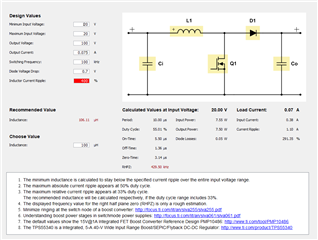
Hi, I tried a circut desgin from the webbench tool to generate 200V out of 20V, but my circut does nothing then reproduce the input voltage.

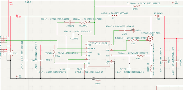
I attach my KiCad pic. Thanks for any help.

  • Hi Matthias,

    Thanks for using the e2e forum.

    Boosting from 20V to 200V is a ratio of x10. This might be more than a boost topology can support, has the maximum duty cycle is limited. (Not only by the device specs, but also by the physical limitation of transferring all the required power to the output side during the short off-time period of the switch)

    There are several possibilities to overcome this.
    The first approach is to design the application to run in DCM. This will reduce the duty cycle, but creates stronger ripple current in the inductor.
    As you are using a 680uH inductor, I would assume you currently designed for CCM operation.
    Can you share your load requirements?
    This will define if a DCM design approach makes sense here.

    Another solution would be to change the topology to a Flyback. Here you can adjust the winding ration of the transformer to achieve lower duty cycle.

    Best regards,
    Niklas

  • Hi Niklas, thank you for your feedback. I need 50 to 75mAmps output or 20W. I know that the ratio is high but the web tool and the specs said that up to 300V are possible… . 
    Some remarks: I tested with no load.

  • Hi Matthias,

    Thanks for the feedback.
    75mA should be low enough that you can achieve this with a DCM circuit.
    As webench cannot calculate for DCM, I would recommend to have a look at our Power Stage Designer calculator.
    https://www.ti.com/tool/de-de/POWERSTAGE-DESIGNER

    This calculator shows the current levels within the inductor and when it enters DCM operation.
    By reducing the inductance or switching frequency, you will reduce the duty cycle but also increase the current ripple and output voltage ripple.
    For example, by using 100kHz switching frequency and a 100uH inductor, you can reduce the duty cycle from 90% down to 55% at max load.

    These might be good starting values for your design.

    Best regards,
    Niklas

  • Hi, solved the issue, i think i had some soldering problems, I did it again and it worked fine. Thanks for your help.