This thread has been locked.

If you have a related question, please click the "Ask a related question" button in the top right corner. The newly created question will be automatically linked to this question.

TPS61092: using TPS61092 in power path application

Part Number: TPS61092
Other Parts Discussed in Thread: TPS610333

Tool/software:

Hi All,

Im planning to use the TPS61092 chip in order to convert:

Vin that could be from 3.7-4.2 Volt when the system is in battery mode
Vin at 5V when in wall adapter 5V mode
Vin is the output of a power path circuit and could be provided by lipo or 5V fixed.

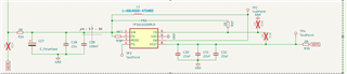
Attached there is my circuit.

Vout : should be 5V max 2A

L1: CDRH103RNP6R8NCB

FB pin: floating

LB1: R33=1.87Mohm, R32=340Kohm

C26 = TPSD107M010R0050 - 100uf

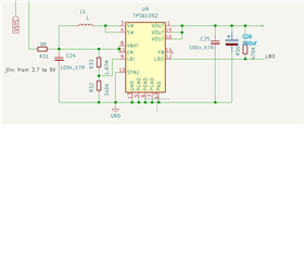
Can you validate the schematic? in particular: will do it work with 5V input? Could be FB pin left floating ?

Thanks a lot

Nicola

  • Hi Nicola,

    Do you need high efficiency under 5V Vin, if you, you could use BUCK BOOST.

    As is mentioned output current could be 2A, TPS61092 is not suitable here, you need a device with higher current limit . any way , FB could be left open,

  • Hi Nini,

    thanks for support. Im not so expert of DC-DC (sorry)

    Anyway, I have decided to switch to TPS61033DRLR (below the schematic).

    I have some doubts: 

    • Whats the MODE pin ? where do i have to connect such pin ?
    • for having 5V fixed can I use PN TPS61033DRLR and not TPS610333 by simply connecting the FB to Vin ?
    • When the VIN=5,2V and V target of TPS61033DRLR  is 5V , can you confirm the Vout will follow the VIN minus some voltage drops on RDS?
    • Regarding the inductor PN XGL4020-471MEC, do you have some other equivalent PN ?

    Thanks a lot.

    Nicola

  • Hi Nicola,

    I will loop in Lei , the expert of this device to help on your question.

    Hi Lei,

    Could you help here?

  • Hi Nicola,

    Whats the MODE pin ? where do i have to connect such pin ?

    Operation mode selection in the light load condition. When it is connected to logic high voltage, the device works in forced PWM mode. When it is connected to logic low voltage, the device works in auto PFM mode.

    for having 5V fixed can I use PN TPS61033DRLR and not TPS610333 by simply connecting the FB to Vin ?

    Yes.

    When the VIN=5,2V and V target of TPS61033DRLR  is 5V , can you confirm the Vout will follow the VIN minus some voltage drops on RDS?

    Yes.

    Regarding the inductor PN XGL4020-471MEC, do you have some other equivalent PN ?

    I think XGL4020-471MEC is already a good choice for your application of Vin min = 3.7V, Vout = 5V, and Iout max = 2A application.

    Regards

    Lei

  • Hi Lei,

    thanks for reply, can you explain difference between the 2 mode ?

    Thanks a lot again.

    Nicola

  • Hi Nicola,

    Please refer to the "8.4.1 PWM Mode" and "8.4.2 Power-Save Mode" in the datasheet, there are detailed descriptions there.

    Regards

    Lei