This thread has been locked.

If you have a related question, please click the "Ask a related question" button in the top right corner. The newly created question will be automatically linked to this question.

LM27762: Using LM27762 to drive ADC Analog Supply AVDD/AVSS -> Light load causes ripple on Vin and Vout+

Part Number: LM27762

Tool/software:

Hello,

I am evaluating if the LM27762 can be used as a bipolar voltage souce for an ADCs AVDD/AVSS.

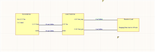
The LM27762 is fed by a 3.3 voltage supplly which als feeds the DVDD of the ADC.

Some reference designs and evaluation boards are doing just that:

https://www.ti.com/tool/TIDA-01434

https://www.ti.com/tool/ADS1235EV

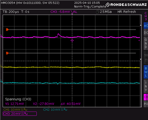
When applying a small load of 1 to 10 mA on Vout+/Vout-, I am measuring a ripple with peak to peak of 37 mV on Vin.

When increasing the load, the frequency shifts from 5 kHz to higher kHz until the ripple is "gone" when a load of 80 to 100 mA is applied.

Ch3 : Vin(purple) Ch1 : Vout+(yellow) Ch2: Vout-(cyan)

Load:1 mA Vin:3.3 V Vout+ : 1.81 Vout- : -1.85

Ch3: Vin; Ch1:Vout +; Ch2: Vout -

Load: 10 mA

no ripple Loard : 90 mA

As you can see, the ripple in Vin is causing a ripple in Vout+ too.

My questions Are:

Can this ripple on Vin be an issue for the DVDD of the adc? Note: I am using the same 3.3 V power supply for LM27762 and the adc DVDD.

Can this ripple have an influence on the measurements taken by the adc? Since The ref. designs above are doing it, my guess is not?

Can the ripple on Vin be reduced?

Regards

Johannes

  • Hi Johannes,

    Thanks for using E2E.

    Could you please provide the schematic and layout for your application. What is the distance between input cap and device input pins (VIN and GND) ?

    Best regards,
    Sepp

  • Hello Sepp,

    At the moment I don't have a schematic. It is more a "learning by doing" approach and I am still figuring out what is affecting what.

    I am using two eval boards which are connect by cables:

    https://www.ti.com/tool/TLV767EVM-014

    https://www.ti.com/tool/LM27762EVM?keyMatch=lm27762&tisearch=universal_search

    • The TLV767EVM outputs are connected to the LM27762EVM with 3.3 V.
    • The LM27762EVM is connected to a resistive load which simulates the adc.
    • Both boards have default configurations.

    I realize, that I did not mention this in my earlier post. Apologies for that.

    Here is a drawing of my setup:

    I assume, that in my case the distance from "input cap" to "device input pins" would be from TVL676EVM outputs to LM27762 inputs.

    Is that correct?

    Your question about the distance got me thinking. By reducing the cable length, the V_Peak_peak of the ripple will probably drop, because the cables length is proportional to inductance.

    I am unsure about the magnitude of the reduction though.

    And even with reduced distances, there will be a ripple on V_in, assuming a load of 1mA to 100 mA.

    Which leaves the following question:

    Does the remaining ripple has a significant influence, when using the LM27762 as a supply for the analog part of an ADC?

    Are my assumptions correct?

    Thank you for time,

    Regards and have a nice weekend :)

    Johannes

  • Hallo Johannes,

    Thanks a lot for the additional data.

    The noise/ringing on the device input which you can see on lower output currents is not coming from the device. It is a LC resonance ringing which is produced by a longer input cable and the input capacitor. This will be not the case on the real application normally. You can reduce this ringing with shorter cables and a 47uF Tantalum cap for more damping on the input of the device on the EVM. On higher output loads the device is continually switching without any pause so the resonance can not start.

    Please see also our app note of using additional filters on DC/DC converters: https://www.ti.com/lit/pdf/slvafe0?keyMatch=slvafe0&tisearch=universal_search

    Best regards,
    Sepp

  • I don't think that there is any issue for the ADC function.

  • Hallo Sepp,

    danke für deine Erklärung Slight smile.

    Thank you for the explanation.