This thread has been locked.

If you have a related question, please click the "Ask a related question" button in the top right corner. The newly created question will be automatically linked to this question.

LMR51430: High output ripple

Part Number: LMR51430
Other Parts Discussed in Thread: TPS563201,

Tool/software:

Hello. 

I created a circuit based on LMR51430YDDCR to get 5V out of ~24V for a measurement application (requires low noise for opamp). Currently the load is only ~20mA. After activation, there will be a CAN transceiver drawing up to 70mA when sending. 

Unfortunately I can observe almost 100mV ripple on the output in low load situations. It becomes better (but still too high) with more load. Therefore I appreciate any recommendation to lower the noise. Is there any general document from TI, that describes how to improve the circuit?
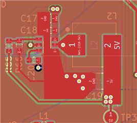
My circuit

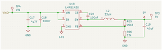
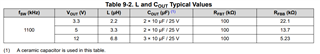
L2 is Coilcraft SRP7050WA-330M

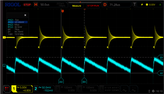
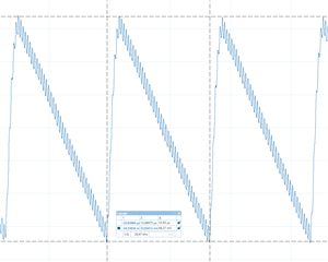
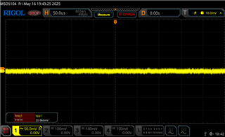
Measured output (yellow) 

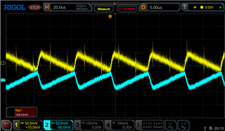
please ignore the peaks - there was an issue with my scope ref GND, which I noticed later.

Many thanks in advance for your help.

  • Hi,

    Few questions: 

    1. Where are you measuring output voltage?

    2. Are you using the EVM? 

    Regards,

    Rahil

  • 1. I am measuring at TP3 - after the capacitor. If it helps, please find below the comparison between TP3 (blue) and the switching node (yellow)

    2. no, it is my own design

  • The layout looks okay to me. What is the max current you are pulling? 

    Regards,

    Rahil

  • Currently only the MCU is running and it's around 30mA. I am planning to have as well a CAN transceiver on the same supply and this will draw up to 70mA (bus dominant) -> Total max will be not more than 150mA

  • Hi Philip,

    How are you measuring ripple? When measuring output voltage ripple it is important to utilize the tip and barrel method directly across the output capacitor to reduce the effect of the probe's loop inductance with its ground wire. Please see below:

    Can you also note what the ESR of the output capacitor is that you are using?

    Thank you,

    Joshua Austria

  • Hi Joshua,

    measuring with the tip GND didn't clear the issue - still 68mV:

    The C19 is a MLCC. I am not sure about ESR. The MPN is GRM32ER61C476KE15L

  • Hi Philip, 

    Thanks for checking that. 

    I checked your schematic and it seems your output inductor is very oversized for this application. You may be introducing instability into your application and thus experience greater than acceptable output ripple. Please see table 9-2 in the datasheet for a more appropriate inductor to capacitor combination for your application. I am including it below for your convenience:

    Please replace your inductor and output capacitor with the combination listed for VOUT = 5V and see if that helps.

    Thank you,

    Joshua Austria

  • Sorry, it took a while until I had the new inductor and time to test. But today I can confirm, that this measure reduced the ripple significantly.

    Before:

    and after (with 3.3uH inductor):

    Thanks a lot for your support!

    Remark: On another board I exchanged the LMR51430 with a TPS563201 (unfortunately this device cannot reach the required input voltages) with the same (big) inductor and it was much less noise, and no superimposed frequency.

  • Hi Philip, 

    You're welcome!

    Yeah that inductor may make sense with that device's internal compensation. However with the LMR51430 because of its internal compensation parameters and design, you are able to utilize a much smaller LC combination to provide a relatively clean, regulated output. 

    Please let me know if you have any other questions.

    Thank you,

    Joshua Austria