This thread has been locked.

If you have a related question, please click the "Ask a related question" button in the top right corner. The newly created question will be automatically linked to this question.

BQ40Z50-R2: Clarification on startup and shutdown conditions

Part Number: BQ40Z50-R2
Other Parts Discussed in Thread: BQ40Z50, BQ25798, BQSTUDIO

Tool/software:

Hi there—our design comprises the BQ25798 with a 1S4P battery pack that uses the BQ40Z50 for primary protection. The BQ40Z50 is configured with the following parameters in our application:

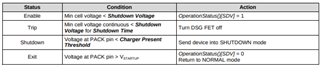
  • CUV threshold = 2700 mV
  • Shutdown threshold = 2600 mV
  • Charger present threshold = 2250 mV
  • SUV threshold = 2000 mV
  • SUV delay = 5 seconds
  • SUV_MODE = 1
  • ZVCHG threshold = 1800 mV

I have replaced the cells in the battery pack with a Keithley 2308 cell simulator to test the interaction between the BQ25798 and the BQ40Z50 during various conditions. The regulated output of the Keithley 2308 is referred to as VCELL in the notes below.

Our system can charge normally for VCELL above 2.0 V, and SUV PF engages for VCELL below 2.0 V. However, I have a couple points of confusion regarding the startup and shutdown conditions of the gauge:

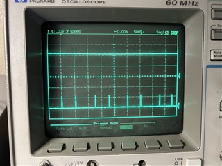
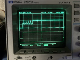
[1] For VCELL = 2.1 V, we see the following waveform at VPACK (channel 1) when a charger is inserted:

The behavior shown here is normal, and can be described as:

  1. 10% through 30% time division: the BQ25798 repeatedly disables and re-enables VPACK because the CHG FET is open at the beginning of the SUV delay, and the BQ25798 thinks charging has terminated. The BQ40Z50 keeps being reset before the SUV delay can complete.
  2. 30% time division: our system firmware intervenes and reduces the charging termination debounce time, so the BQ25798 can hold VPACK steady.
  3. 30% through 40% time division: the BQ40Z50 waits for the SUV delay to expire.
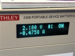
  4. 40% time division: the BQ40Z50 closes the CHG FET, and charging proceeds normally with VPACK = VCELL = 2.1 V. The cell simulator display confirms the cell is drawing the expected precharge current (500 mA in our application).

Originally, I feared that the gauge would shut down at 40% time division because VPACK is less than the charger present threshold, and VCELL is less than the shutdown voltage. To my relief, however, the gauge stays awake and the CHG FET can stay closed.

What is keeping the gauge awake in this case? Is there some other condition (charge current flowing?) during which the gauge will avoid shutting down? To be clear, what we're seeing here is desired behavior—I just want to make sure there are no other flash parameters we need to set to ensure this behavior can be consistent.

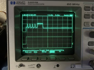
[2] I disabled SUV PF, then repeated my test with VCELL lowered to 1.9 V; the result looks similar to below:

In this case, the CHG FET never closes and the cell cannot charge. This is ultimately not a problem, since we would normally trigger SUV at this level of VCELL anyway.

I can still communicate with the gauge over I2C, since VPACK is close to 4.4 V. The gauge reports the following values during this time:

  • SafetyStatus (0x51): 0x01 0x00 0x00 0x00 (CUV = 1)
  • PFStatus (0x53): 0x00 0x00 0x00 0x00 (none)
  • OperationStatus (0x54): 0x81 0x6d 0x00 0x00 (XCHG = XDSG = SS = SDV = 1)

It seems that whatever mechanism keeps the gauge awake during [1] finally drops out once VCELL approaches 2.0 V. If the gauge can keep the CHG FET closed at VPACK = VCELL = 2.1 V, why can't it do the same for VPACK = 4.4 V?

Thank you in advance for your support—in case I can clarify any of my questions or observations, please let me know.

  • Hi Jeff,

    I am a little confused on what is going on here. For situation [1] the SUV protection is a Permanent Fail, meaning the only way for this to be cleared by the gauge would be by reset. Do you have the [SUV_MODE] bit set at this time?

    For situation [2], typically if the gauge is in shutdown the FETs will be open. Based on the operation status, the gauge is reflecting that this shutdown was caused by a Voltage Based Shutdown, where the voltage needs to be less than the Shutdown Voltage, but won't enter if the voltage is greater than the Charger Current Threshold, hence why I believe you are able to communicate at this time. Is it possible to get a full log of this situation? The charge FET is being limited by XCHG at this time, but I do not believe this could be caused by the shutdown. There could be something else creating this XCHG call.

    Regards,

    Anthony

  • Hi Anthony—thanks again for your continued support!

    Just to clarify—there is no SUV fault in scenario [1], as VCELL = 2100 V and the SUV threshold is 2000 mV. The only reason I mention SUV is to explain why the charge FET is open for 5 seconds between time divisions 30% and 40%. This is because SUV_MODE = 1.

    What I ultimately mean to ask in scenario [1] is how the gas gauge stays awake while VPACK = VCELL = 2100 mV, both of which are below the shutdown threshold (2600 mV) and the charger present threshold (2250 mV). It seems there is some third condition during which the gauge will avoid shutting down.

    Your explanation for scenario [2] makes sense—my confusion is ultimately why XCHG isn't engaged for scenario [1] if it's engaged for scenario [2]. We ultimately have two requirements:

    • If no charger is connected and VCELL falls below 2600 mV, the gauge must shut down.
    • Charging must be supported for VCELL down to 2000 mV.

    Both of these requirements seem to be met. However, I would have guessed that the charger present threshold must be below 2000 mV for the gauge to accommodate the second requirement, since VPACK = VCELL while XCHG = XDSG = 0 (i.e. both FETs are effectively shorted).

    What we're ultimately trying to understand is whether we need to adjust our charger present threshold, or whether it's fine to leave at 2250 mV. My bench is currently tied up in another test, but I will provide full BQStudio dumps for both scenarios [1] and [2] on Monday.

  • Hi Anthony—I've attached instantaneous logs for scenarios [1] and [2] (i.e. VCELL = 2.1 V and 1.9 V), respectively. I've also attached the flash configuration used for both tests.

    Both logs show the SDV flag is set, which makes sense as the gauge measures VCELL to be 2169 mV and 1898 mV for scenarios [1] and [2], respectively. What's unclear is why XCHG is also set in scenario [2]—none of the conditions defined in the TRM as being able to set XCHG are true. It almost seems as though the XCHG flag has some undocumented dependency on VCELL > V_STARTUP.

    Also unclear is why the gauge doesn't enter shutdown in scenario [1] once both FETs close and VPACK is pulled to VCELL, both of which are below the charger present and shutdown thresholds. As I mention, I originally assumed I should set the charger present voltage below the minimum VCELL voltage we expect to encounter, since VPACK = VCELL once both FETs close.

    To give some additional context—we have an internal deadline to lock the golden file for an upcoming design this week, and any potential changes are time sensitive. If the charger present threshold or any other parameters must change to ensure the (intended) behavior we see in scenario [1] is repeatable, we need to implement them ASAP.

    Thanks again for your continued support—in case I can provide any additional information, please let me know.loose-pcm-mod.gg.csv

    Device Version Info = 4500_2_11
    BQZ Device Name = bq40z50R2
    BQZ Firmware Version = V2_11_BLD52
    
    Design Capacity = 25200
    Design Voltage = 3870
    Specification Info = 0x0031
    Manufacturer Date = 1980-1-1
    Serial Number = 0x0001
    Manufacturer Name = GreatPower
    Design Name = GSP30103123HV V0
    Design Chemistry = LION
    
    Sample,DateTime,ElapsedTime,ManufAccess,RemCapAlarm,RemTimeAlarm,BattMode,@Rate(@),@TimeFull,@TimeEmpty,@RateOK,Temperature,Voltage,Current,AvgCurr,MaxErr,RSOC,ASOC,RemCap,FullChgCap,RunTimeEmty,AvgTimeEmty,AvgTimeFull,ChgCurr,ChgVolt,BattStat,CycleCnt,MaxTurboPwr,SusTurboPwr,MaxTurboCurr,SusTurboCurr,SoH,OpStatA,OpStatB,TempRange,ChgStat,GaugeStat,ITStat,MfgStat,SafetyAlertAB,SafetyAlertCD,SafetyStatAB,SafetyStatCD,PFAlertAB,PFAlertCD,PFStatAB,PFStatCD,CellVolt1,CellVolt2,CellVolt3,CellVolt4,vBAT,vPACK,CellCurr1,CellCurr2,CellCurr3,CellCurr4,CellPower1,CellPower2,CellPower3,CellPower4,Power,AvgPow,IntTemp,TS1Temp,TS2Temp,TS3Temp,TS4Temp,CellTemp,FETTemp,GaugeTemp,FltRemQ,FltRemE,FltFullChgQ,FltFullChgE,NoLoadRemCap,TrueRemQ,TrueRemE,InitialQ,InitialE,TrueFullChgQ,TrueFullChgE,T_sim,T_ambient,RaScale1,RaScale2,RaScale3,RaScale4,CompRes1,CompRes2,CompRes3,CompRes4,PackGrid,LStatus,CellGrid1,CellGrid2,CellGrid3,CellGrid4,StateTime,DOD0_1,DOD0_2,DOD0_3,DOD0_4,DOD0 Passed Q,DOD0 Passed E,DOD0 Time,DODEOC_1,DODEOC_2,DODEOC_3,DODEOC_4,QMax1,QMax2,QMax3,QMax4,QMaxDOD0_1,QMaxDOD0_2,QMaxDOD0_3,QMaxDOD0_4,QMaxPassedQ,QMaxTime,Tk,Ta,RawDOD_1,RawDOD_2,RawDOD_3,RawDOD_4,CBTime1,CBTime2,CBTime3,CBTime4,CBDOD_1,CBDOD_2,CBDOD_3,CBDOD_4,CBTotalDODChg,SOH_FC_Q,SOH_FC_E,LogRowTime(ms),LogStatus
    1,DateTime,11.58,0x2D87,300,10,0x6001,0,65535,65535,1,29.2,2169,478,474,1,0,0,0,14587,65535,65535,1845,500,4450,0x0090,0,-1398,-1398,-4993,-4993,58,0x2D87,0x0000,0x08,0x0001,0x15,0x0014,0x0158,0x0000,0x0000,0x0001,0x0000,0x0000,0x0000,0x0000,0x0000,2170,0,0,0,2171,2177,480,0,0,0,104,0,0,0,104,103,25.1,24.5,24.3,25.9,29.2,29.2,-273.1,29.2,65006,65388,14587,5066,9,65006,65387,14588,5066,14587,5066,27.7,27.6,1000,0,0,0,0,0,0,0,0,14,0,0,0,0,68,16384,0,0,0,65527,65534,0,2336,0,0,0,17642,16350,16350,16350,0,0,0,0,65527,0,100,1000,16384,0,0,0,0,0,0,0,0,0,0,0,0,14494,5008,112,SUCCESS
    
    Device Version Info = 4500_2_11
    BQZ Device Name = bq40z50R2
    BQZ Firmware Version = V2_11_BLD52
    
    Design Capacity = 25200
    Design Voltage = 3870
    Specification Info = 0x0031
    Manufacturer Date = 1980-1-1
    Serial Number = 0x0001
    Manufacturer Name = GreatPower
    Design Name = GSP30103123HV V0
    Design Chemistry = LION
    
    Sample,DateTime,ElapsedTime,ManufAccess,RemCapAlarm,RemTimeAlarm,BattMode,@Rate(@),@TimeFull,@TimeEmpty,@RateOK,Temperature,Voltage,Current,AvgCurr,MaxErr,RSOC,ASOC,RemCap,FullChgCap,RunTimeEmty,AvgTimeEmty,AvgTimeFull,ChgCurr,ChgVolt,BattStat,CycleCnt,MaxTurboPwr,SusTurboPwr,MaxTurboCurr,SusTurboCurr,SoH,OpStatA,OpStatB,TempRange,ChgStat,GaugeStat,ITStat,MfgStat,SafetyAlertAB,SafetyAlertCD,SafetyStatAB,SafetyStatCD,PFAlertAB,PFAlertCD,PFStatAB,PFStatCD,CellVolt1,CellVolt2,CellVolt3,CellVolt4,vBAT,vPACK,CellCurr1,CellCurr2,CellCurr3,CellCurr4,CellPower1,CellPower2,CellPower3,CellPower4,Power,AvgPow,IntTemp,TS1Temp,TS2Temp,TS3Temp,TS4Temp,CellTemp,FETTemp,GaugeTemp,FltRemQ,FltRemE,FltFullChgQ,FltFullChgE,NoLoadRemCap,TrueRemQ,TrueRemE,InitialQ,InitialE,TrueFullChgQ,TrueFullChgE,T_sim,T_ambient,RaScale1,RaScale2,RaScale3,RaScale4,CompRes1,CompRes2,CompRes3,CompRes4,PackGrid,LStatus,CellGrid1,CellGrid2,CellGrid3,CellGrid4,StateTime,DOD0_1,DOD0_2,DOD0_3,DOD0_4,DOD0 Passed Q,DOD0 Passed E,DOD0 Time,DODEOC_1,DODEOC_2,DODEOC_3,DODEOC_4,QMax1,QMax2,QMax3,QMax4,QMaxDOD0_1,QMaxDOD0_2,QMaxDOD0_3,QMaxDOD0_4,QMaxPassedQ,QMaxTime,Tk,Ta,RawDOD_1,RawDOD_2,RawDOD_3,RawDOD_4,CBTime1,CBTime2,CBTime3,CBTime4,CBDOD_1,CBDOD_2,CBDOD_3,CBDOD_4,CBTotalDODChg,SOH_FC_Q,SOH_FC_E,LogRowTime(ms),LogStatus
    1,DateTime,4.28,0x6D81,300,10,0x6001,0,65535,65535,1,28.7,1898,0,0,1,0,0,0,14599,65535,65535,65535,0,0,0x02D0,0,-1398,-1398,-4993,-4993,58,0x6D81,0x0000,0x08,0x0001,0x55,0x0014,0x0158,0x0000,0x0000,0x0001,0x0000,0x0000,0x0000,0x0000,0x0000,1898,0,0,0,1899,4397,0,0,0,0,0,0,0,0,0,0,25.5,24.9,24.9,26.1,28.7,28.7,-273.1,28.7,65008,65388,14599,5081,0,65008,65388,14600,5081,14599,5081,28.7,28.6,1000,0,0,0,0,0,0,0,0,14,0,0,0,0,123,16384,0,0,0,0,0,0,2336,0,0,0,17642,16350,16350,16350,0,0,0,0,0,0,100,1000,16384,0,0,0,0,0,0,0,0,0,0,0,0,14494,5008,106,SUCCESS
    

  • Hi Jeff,

    Sorry for the delay, a couple thoughts here:

    What I ultimately mean to ask in scenario [1] is how the gas gauge stays awake while VPACK = VCELL = 2100 mV, both of which are below the shutdown threshold (2600 mV) and the charger present threshold (2250 mV). It seems there is some third condition during which the gauge will avoid shutting down.

    I'm curious whether this is being caused by the VPACK still seeing a voltage that can clear VStartup (condition to exit shutdown) to where its entering and exiting almost immediately. 2100mV is within the bounds of the Vstartup, so would it be possible to drop this slightly out of the bounds of Vstartup (under 2050mV, preferably around 1900mV to be safe) for both VCELL and VPACK to see if there is any change to the behavior here?

    What we're ultimately trying to understand is whether we need to adjust our charger present threshold, or whether it's fine to leave at 2250 mV. My bench is currently tied up in another test, but I will provide full BQStudio dumps for both scenarios [1] and [2] on Monday.

    I believe the Charger Present Threshold value is ok here since in both situations it is being cleared, and both are opening the DSG FET at this time. The only thing I can think of here based on the logs that would disable the CHG FET is if a PF was triggered, but there's no sign of a PF event here. Does sending the PF_CLEAR command at this time do anything?

    Regards,

    Anthony

  • Hi Anthony—thank you for the update; no worries!

    I think my confusion surrounding [1] is actually due to a small error in the TRM, or at least my interpretation of it. The datasheet claims that both the startup and shutdown thresholds are fixed in HW:


    This matches my observation. On the contrary, the TRM claims that only the startup threshold is fixed in HW, while the shutdown threshold is defined by the charger present threshold:

    This does not match my observation, and it seems at least one other customer has encountered this same discrepancy too. I suspect the charger present threshold defined in flash does not impact startup and shutdown, and instead impacts only FW-controlled mechanisms such as MFC or emergency FET shutdown.

    Regarding your request to pull both VCELL and VPACK down to 1900 mV—because the CHG FET is opening for VCELL < V_STARTUP despite VPACK > V_STARTUP as described in scenario [2] , I cannot perform this experiment. I can only control VCELL using the cell simulator, and VPACK must naturally follow it while the CHG FET is closed. The charger in our application (BQ25798) does not have granular control over VPACK during this condition.

    On that topic—I did try sending a PF_CLEAR command (0x29) while VCELL < V_STARTUP, VPACK > V_STARTUP and XCHG = 1 as in scenario [2], but XCHG remains set, and the CHG FET remains disabled. As you correctly mention, there is no PF present in this case, so this seems expected.

    With none of the functions described in the TRM seemingly responsible for XCHG = 1 in scenario [2], I loosely suspect a HW mechanism may be responsible here. The datasheet seems to suggest that the CHG FET charge pump driver is powered from VCELL and not VPACK—perhaps if VCELL is too low, the CHG FET charge pump driver is disabled by design such that XCHG = 1.

    Ultimately, the gauge seems to be behaving in a predictable manner that satisfies our requirements, so it doesn't seem any further changes are required. If you are able to provide any insight about the two hypotheses I've shared behind scenarios [1] and [2] based on the IC design, however, it will alleviate our concern that we're missing anything else.

  • Hi Jeff,

    I think my confusion surrounding [1] is actually due to a small error in the TRM, or at least my interpretation of it. The datasheet claims that both the startup and shutdown thresholds are fixed in HW:


    This matches my observation. On the contrary, the TRM claims that only the startup threshold is fixed in HW, while the shutdown threshold is defined by the charger present threshold:

    I am aligned with you here, I will reach out to our hardware team to get confirmation on this topic and get back to you.

    On that topic—I did try sending a PF_CLEAR command (0x29) while VCELL < V_STARTUP, VPACK > V_STARTUP and XCHG = 1 as in scenario [2], but XCHG remains set, and the CHG FET remains disabled. As you correctly mention, there is no PF present in this case, so this seems expected.

    With none of the functions described in the TRM seemingly responsible for XCHG = 1 in scenario [2], I loosely suspect a HW mechanism may be responsible here. The datasheet seems to suggest that the CHG FET charge pump driver is powered from VCELL and not VPACK—perhaps if VCELL is too low, the CHG FET charge pump driver is disabled by design such that XCHG = 1.

    Ultimately, the gauge seems to be behaving in a predictable manner that satisfies our requirements, so it doesn't seem any further changes are required. If you are able to provide any insight about the two hypotheses I've shared behind scenarios [1] and [2] based on the IC design, however, it will alleviate our concern that we're missing anything else.

    Interesting, then this might be pointing to something internally with the gauge that is throwing this XCHG that isn't exactly an event (I believe this might be tied to the HW shutdown threshold we are seeing above) however I think our design team would be able to shed more light on what is happening internally.

    Regards,

    Anthony

  • Hi Anthony—just checking in to see whether you were able to find out anything about these two issues. In case I can provide any additional information, please let me know.

  • Hi Jeff,

    Sorry for the delay, I was able to get a little more clarification from our team on these items:

    [1]: The device actually has a hardware and a firmware shutdown state, with the hardware shutdown being depicted in the datasheet. The hardware shutdown is entered via the Vpack being lower than the Vshutdown value, where the device will switch from being powered by BAT to VCC. This state also allows for 0-V charging. 

    [2]: For this scenario (Vcell to 1900mV), I believe you are right that this is a hardware mechanism being caused by entering the hardware shutdown state. Since the CHG and DSG pumps are driven by the voltage from BAT, along with the device power source switching from BAT to VCC, I believe this could play a part in it, however I would need to confirm with design.

    Regards,

    Anthony

  • Hi Anthony—thank you for the update!

    I'm aligned with you about [1] in that there are separate HW and FW shutdown states, and the mechanics of HW shutdown seem clear and consistent. What is not clear are the mechanics of FW shutdown—the TRM seems to imply that VPACK < Charger Present Threshold is sufficient to place the gauge into FW shutdown, but this is not the behavior we're seeing.

    The Charger Present Threshold does not seem to have any impact on the state of the gauge so long as VCELL is sufficiently high. It seems some kind of exception is present that overrides entry into FW shutdown based on VPACK relative to the Charger Present Threshold—ultimately, we'd like to understand what these exception(s) are so that we don't inadvertently bypass them.

    Please forgive me, but I may not completely follow about [2]—the gauge is not in HW shutdown in this case, as VPACK > V_STARTUP and we can still communicate with the gauge over I2C. It seems there is a hidden relationship between VCELL and the ability for the CHG FET to close, and this window into the design is what we're hoping to glean from this thread.

    Thanks again for your continued support—in case I can clarify any of my questions or comments, please let me know.

  • Hi Jeff,

    Sorry for the delay, just to try and wrap my head around this situation again:

    [1]: VCELL = VPACK = 2.1V 

    Device stays awake even though the Charger Present Threshold and FW Shutdown Voltage parameter conditions are met.

    Since VPACK is staying in that grey area between both the HW Shutdown voltage thresholds and the Start-up voltage thresholds, would it be possible to check what is occurring on the TS1 pin at this time? Maybe it could potentially be falling in and out of HW shutdown at this time.

    Regards,

    Anthony

  • Hi Anthony—no problem; I will provide this waveform early next week.

  • Hi Jeff,

    Thanks for the update, please share the waveform when available.

    Regards,

    Anthony

  • Hi Anthony—thank you for accommodating some delay on my side; I needed a little bit of time to set up this measurement again. Please find the results below:

    Channel 1 (top) is VPACK (2.1 V) = VCELL, while channel 2 (bottom) is the voltage measured at the TS1 pin. The amplitude of the pulse train is 600 mV—the measurement was taken at room temperature, so the NTC resistance would have been roughly 10k; the amplitude seems reasonable.

    It looks as though the period consistently alternates between 500 ms and 750 ms; it does not vary beyond this pattern. Please note that our design enables all four TSx pins in case this affects the sampling rate of the TS1 pin.

    The waveform suggests the internal pull-up resistor is briefly enabled at a predictable rate, so it does not seem as though the gauge is falling in and out of shutdown. This is corroborated by the fact that I2C communication is always reliable. In case I have misunderstood, please let me know.

    Furthermore, note that our design sets SUV_MODE = 1. If the gauge were entering and exiting shutdown, we would see the CHG FET open for 5 seconds each time. In this case, the CHG FET is always open; this is made apparent by the fact that the cell simulator (i.e. DC power supply) used in place of the cells consistently sinks the BQ25798 precharge current selected for our design (480 mA):

    Does the gauge FW give any clue as to why the Charger Present Threshold seems to have no impact here? Apologies for continuing to dig here—this is a unique case where the gauge inexplicably meets our requirements, so we're a bit nervous to seal the gauge without understanding why it's working the way it is. Thanks again!

  • Hello Jeff,

    We have received your update and are working on your response.

    Thank you,
    Alan