This thread has been locked.

If you have a related question, please click the "Ask a related question" button in the top right corner. The newly created question will be automatically linked to this question.

TPS7B86-Q1: CAN transmission fail during Bulk Current injection testing.

Part Number: TPS7B86-Q1

Tool/software:

Hello

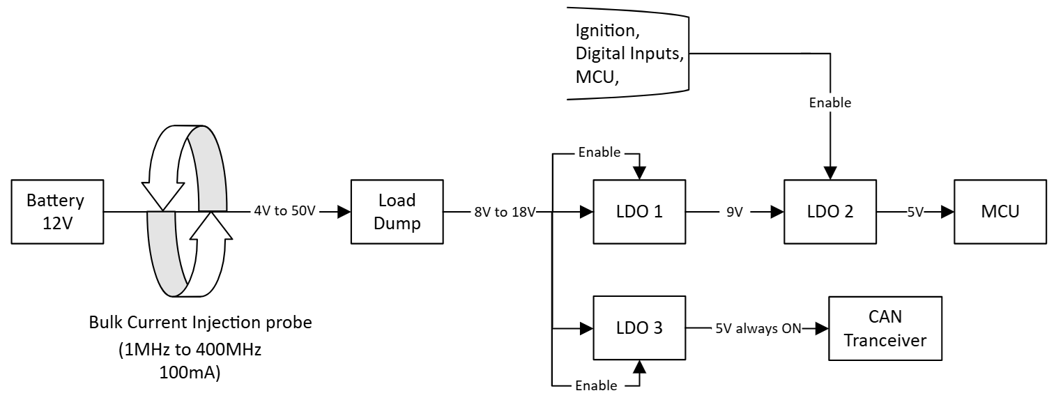
Below is the block diagram of power section. Product fails (CAN transmission gets interrupted) during BCI testing. 

Capacitor used in

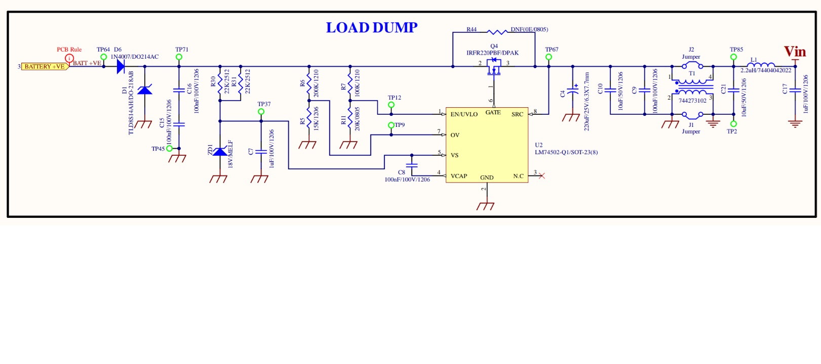
  • Load dump output is 1uF/50V/1206
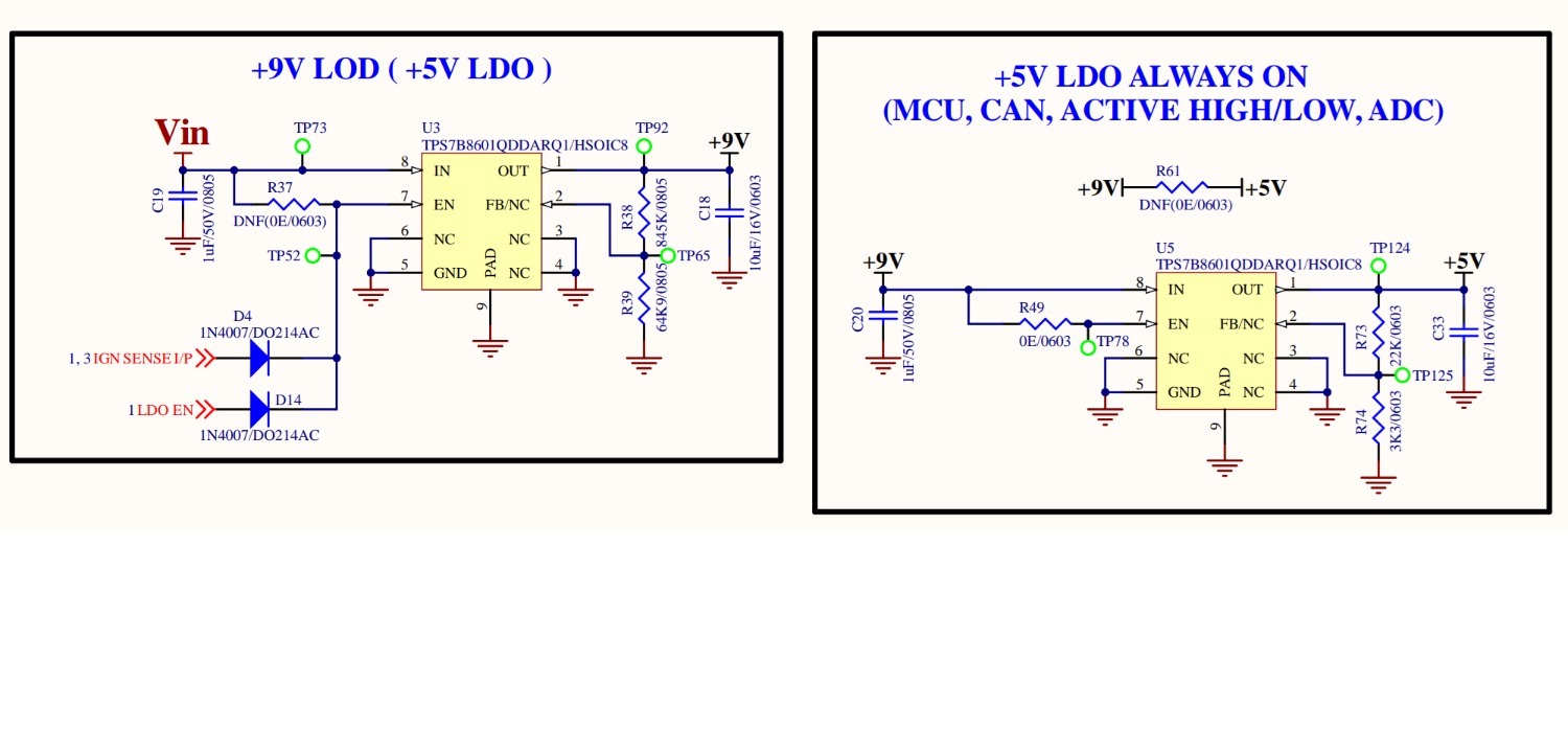
  • LDO 1 input is 1uF/50V/0805
  • LDO 1 output is 10uF/16V/0603
  • LDO 2 input is 1uF/50V/0805
  • LDO 2 output is 10uF/16V/0603
  • LDO 3 input is 1uF/50V/0805
  • LDO 3 output is 10uF/16V/0603

What is the possible cause?

  • Hi Kapeesh,

    Are all the devices, TPS7B86? Are you using the fixed or the adjustable version? If adjustable versions are used, could you please share the resistor values with me for the divider?

    Are you using an input filter for HF noise filtering?

    Regards

    Ishaan

  • Hi Ishaan,

    Yes, all devices are TPS7B86-Q1 (adjustable variant). We are using a CMC and PI filter after load dump section (refer below schematic for resistance value and filter details.

    Thanks

    Kapeesh

  • Hi Kapeesh,

    Please ensure your PI filter is low pass and has a cutoff frequency lower than the first frequency at which BCI fails

    Please use a combination of capacitors at each LDO input which is also common analog practice. You would need multiple decoupling capacitors in parallel (1uF OR 10 uF + 0.1uF + 0.01uF) depending on the Frequency range of the test to suppress noise on the VS pin.

    You can add a feedforward capacitor (Cff) on LDO1 and LDO3 and if required, on LDO2 to suppress noise and pass the HF injection

    Some suggestions on layout:

    • Good input filter circuit can suppress the BCI noise, TI recommends to place input capacitors as close to device pins as possible.
    • Vias will introduce parasitic noise, TI recommends to use as less vias as possible especially on power traces.
    • Large GND polygon can provide a good noise path and thermal performance, TI recommends to merge GND together and keep it as large as possible.

    Best Regards

    Ishaan