This thread has been locked.

If you have a related question, please click the "Ask a related question" button in the top right corner. The newly created question will be automatically linked to this question.

LP5810: About LP5810 Operation

Part Number: LP5810

Tool/software:

Hello,

I am an FAE at a distributor that handles TI products.
I received the inquiry from my customer about the LP5810.
(Question)
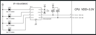
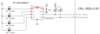
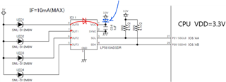
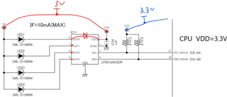
In the attached circuit, even when the 3.3V is removed (turned off), VCC does not become 0V, and a voltage of about 2.4V remains.
When the 5V is turned off, VCC becomes 0V, so there is a possibility that voltage is leaking from the 5V voltage to VCC.
Is this situation correct?
I don't know the internal configuration of the device, so I would appreciate your opinion.
Also, if this situation is correct, is there any way to prevent the 5V voltage from leaking into VCC?

Best regards,

  • Hi Kaji,

    Our expert will give you feedback later.

  • Hi Kaji,

    Yes, the measurement is correct. As there is an internal body diode connected between every OUTx and VCC. 

    May I know why customer wants to prevent the 5V pull up VCC?

    Best regards,

    Felix

  • While I'm not the original customer, we hit this same issue. 

    LEDs are powered by USB and all I2C devices are on their own 3V3 power domain. The external domain is controlled by our main MCU which will enable the 3V3 power at initialisation, and we can power cycle 3V3 to force the I2C devices to reset.

    The end result is that as soon as we connect 5V to the board for flashing the 5V jumps through the led and body diodes to the 3V3 domain. Luckily the red led drops the voltage to just about 3V3 so it doesn't outright fry the board, but we're concerned about potential damage to LED and LP5810 because of excess current through this path. 

    What would be your recommended fix to our PCB design? 

    I would also ask you to mention the body diode in the data sheet, and mark the OUTx absolute maximum voltage as 0 ... VCC + 0.3V or so. Right now the recommended voltage on OUTx is listed as 0 ... 5.5V  without a mention to VCC. 

  • Hi Otso,

    Recommend two methods,

    1. Connect a serial diode between 3.3V and VCC of LP5810.

    2. Connect the VCC to the VLED (power supply connected to the anode of LED) to USB 5V. The SCL/SDA are still pulled up to the 3.3V (as the high/low threshold is not related to VCC). By sending software reset cmd to reset the LP5810

    Thanks for your suggestion, will discuss internally to decide how to mention the body diode in datasheet.

    best regards,

    Felix