This thread has been locked.

If you have a related question, please click the "Ask a related question" button in the top right corner. The newly created question will be automatically linked to this question.

BQ25302: VBUS loss not detected at higher currents

Part Number: BQ25302

Tool/software:

Hi

We are using the BQ25302 in a setup similar to the one in the datasheet:

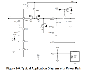
The difference is that we are using REGN to switch Q4. Our charging current is 1A.

When we unplug the USB connector, VBUS and REGN go down to zero as expected when we have no additional load at VSYS. When we add 1A of additional external load at VSYS, VBUS and REGN change to battery voltage when the USB connector is unplugged. It seems that switching off Q1 does not work anymore and the battery keeps VBUS and therefore REGN alive through Q2 and Q1. And because REGN is still alive, Q4 is not switching and our circuit is not working as expected

We can reproduce that it is load dependent: The limit is somewhere around 0.9A - 1A (plus charging current of 1A).

Any idea what can cause this problem and how we can solve it?

Thank you!

  • Hi,

    1. The device is not designed for supporting much load from the PMID pin.
    2. One workaround is to set /EN high to enable the charger so that /EN goes low (i.e. disable charger) when VBUS goes to low.

    Thanks,

    Ning.

  • Hi

    Thank you for the answer. I made some measurement yesterday and it seems that the problem could be solved using the diode at the gate of Q4 (Figure 9.6). However, I don't yet fully understand why this happens only with higher current.

    But I'm a bit confused about your statement that the device is not designed for "much load from the PMID pin". For me, the whole idea of the setup in Figure 9.6 is based on the fact than the device can switch between battery or VBUS mode and therefore must support load current at the PMID output.

    "PFET Q4 turns off when VBUS is plugged in and VSYS is supplied from VBUS/PMID." There is even a load regulation between the current on PMID and the charging current:

    So is it really true that the device is not capable to deliver the 2.25A (I_NDPM) on the PMID pin?

  • Hi,

    IINDPM refers to the current going into the VBUS pin, not the current going out of the PMID pin.

    Thanks,

    Ning.

  • Thank your for the answer.
    Which current is allowed on the PMID pin? I couldn't find any information in the datasheet. Figure 9-6 indicates that I can at least power up the system through PMID, it would be important to know the maximum current for our design.

  • Hi,

    We will get back to you early next week.

    Thanks,

    Ning.

  • Hic

    As mentioned earlier, it is not recommended to connect load at the PMID pin. If the application needs to connect some PMID load, please set /EN high to enable the charger so that /EN goes low (i.e. disable charger) when VBUS goes to low.

    Thanks,

    Ning.

  • Hi
    I can confirm that it is really a problem of then current flowing out of PMID. Bypassing this current solves the problem. Thank you for the answer.

    A remark in the datasheet would be helpful, there is no specification for the current for the PMID pin.