This thread has been locked.

If you have a related question, please click the "Ask a related question" button in the top right corner. The newly created question will be automatically linked to this question.

BQ25750: BQ25750 as e-bike charger

Part Number: BQ25750
Other Parts Discussed in Thread: BQ25756

Tool/software:

Hello,

we are trying to charge an e-bike battery with a custom board using the BQ25750 charger.

We have tested the board with various lipo cells number combinations and it operates correctly.

The problem arises when we try to charge an ebike battery pack. The specific pack is the RPH0002 which is a 54.6V battery pack.

The input voltage for the BQ25750 is 24V with sufficient current.

The problem is that the charger is not starting. This pack has BMS inside and different port for charging and at these pins has zero Volts.

We have disabled the precharge and the termination cycles but still nothing. It seems that the BQ25750 is not starting when it sees 0V at the feedback resistor.

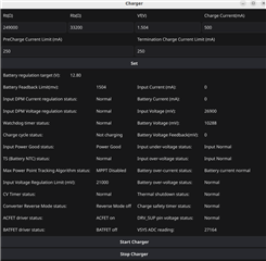
All the status registers of the chip are clear. Please check the screenshot attached.

We tested the battery pack with its own charger and it charges correctly.

Does anybody has any idea how to save this design?

Thank you.

  • Hello Ioannis,

    Thanks for working on this. Just to make sure I'm reading your message correctly, you're measuring 0V at the output of the BQ25750 with the following conditions:

    • EN_PRECHRG=0
    • EN_TERM=0
    • The battery pack is connected.

    I have a few questions to help debug this.

    1. Is there any voltage on the battery pack?
    2. Can you recheck if the BQ25750 can charge without the battery pack connected?
    3. Are the charge / discharge FETs of the battery pack open or closed?

    Also, I would recommend removing the BATFETs from the BQ25750 or using the BQ25756 to charge the battery. The inrush current from a 54V battery can damage the BATFETs on the BQ25750. We have an FAQ on the BQ25750 power path switchover for more information.

    Best Regards,
    Ethan Galloway

  • Hello Ethan,

    thank you for your reply.

    I will try to make it more clear.

    The battery pack is an e-bike battery with internal BMS. This pack has different port pins for charging. I measured the voltage at these pins and it is zero when the battery is not connected to the charger.

    What I did:

    • I connect the output of BQ25750 to the charging port of the battery pack. The voltage is zero.
    • I set EN_PRECHRG=0 and EN_TERM=0 and I enable the BQ25750. The voltage is still zero, not charging.
    • I connect the original ebike's charger AC/DC pack and the battery is charging correctly. This charger has 54.6 V output when it is unconnected.

    We have not used FETs for the battery or AC input. I understand  that the BQ25756 is more suitable but I think that the problem will be the same. I attached the schematics.

    We have tested the design with only 1 cell and also with 4 cells in series and it worked very well. I have the feeling that the BQ25750 can't start charging when it sees 0V at the battery. It this true? Is it better to use a CC/CV boost DC/DC like a LEDs controller?

    Best Regards,

    Ioannis Gkragkopoulos

    4747.main.pdf

  • Hello Ioannis,

    Thanks for the clarification. I'll review your schematic later on this week.

    For the battery's own charger, have you made sure this is possible? What type of plug does the original ebike's charger have and are there 2 pins or 3 pins? I'm wondering if this battery's BMS has to have a signal from the battery charger to start charging.

    I have the feeling that the BQ25750 can't start charging when it sees 0V at the battery. It this true?

    The BQ25750 should be able to start up when there's 0V at the output. It's odd that the BQ25750 doesn't.

    Can you take a few measurements to help debug this?

    • When the battery is connected and the BQ25756 is charging, what's the voltage on the CE pin?
    • What's the voltage on REGN?
    • What's the voltage on VAC and VFB?

    Best Regards,
    Ethan Galloway

  • Hi Ethan,

    The situation started to get even worse. Now we can’t charge even  a simple pack of Lipo with three cells in series, although we managed to do it last week.

    Below are some measurements we did for the three cells pack :

    • The CE is in 3.3V but we have disabled the CE pin from the register.
    • The VAC is 27V.
    • The VFB is 1.232V but when I read the corresponding register it gives 0V!! (check the attached photo and txt file)
    • The three cells pack voltage is 10.52V (12.6V fully charged)
    • The REGN pin has almost zero volts (136 mV). We use separate regulator for the gate driver supply for all FETs. The output of the regulator is 10V.
    • We use this part TK5R1A08QM for switching FETs (attached is the datasheet).

    All the attachemnts correspond to the three cells pack:

    • A txt file with the values of all registers when the charger is enabled.
    • A screenshot of the GUI, that we use to control the charger, while the charger is enabled.

    About the ebike’s battery connector it is a typical cylindrical connector with two pins and two wires.

    Is it possible we damaged the chip?

    Best Regards,

    Ioannis Gkragkopoulos

    REG0x00_Charge_Voltage_Limit: 0x0000
    REG0x02_Charge_Current_Limit: 0x2800
    REG0x06_Input_Current_DPM_Limit: 0x4006
    REG0x08_Input_Voltage_DPM_Limit: 0x6810
    REG0x0A_Reverse_Mode_Input_Current_Limit: 0x4006
    REG0x0C_Reverse_Mode_System_Voltage_Limit: 0xE803
    REG0x10_Precharge_Current_Limit: 0x1400
    REG0x12_Termination_Current_Limit: 0x1400
    REG0x14_Precharge_and_Termination_Control: 0x00
    REG0x15_Timer_Control: 0x00
    REG0x16_Three_Stage_Charge_Control: [0]
    REG0x17_Charger_Control: 0xD9
    REG0x18_Pin_Control: 0xC0
    REG0x19_Power_Path_and_Reverse_Mode_Control: 0x20
    REG0x1A_MPPT_Control: 0x20
    REG0x1B_TS_Charging_Threshold_Control: 0x96
    REG0x1C_TS_Charging_Region_Behavior_Control: 0x57
    REG0x1D_TS_Reverse_Mode_Threshold_Control: 0x40
    REG0x1E_Reverse_Undervoltage_Control: 0x00
    REG0x1F_VAC_Max_Power_Point_Detected: 0x00
    REG0x21_Charger_Status_1: 0x00
    REG0x22_Charger_Status_2: 0x80
    REG0x23_Charger_Status_3: 0x02
    REG0x24_Fault_Status: 0x00
    REG0x25_Charger_Flag_1: 0x00
    REG0x26_Charger_Flag_2: 0x00
    REG0x27_Fault_Flag: 0x00
    REG0x28_Charger_Mask_1: 0xEB
    REG0x29_Charger_Mask_2: 0xFB
    REG0x2A_Fault_Mask: 0xFE
    REG0x2B_ADC_Control: 0x00
    REG0x2C_ADC_Channel_Control: 0x00
    REG0x2D_IAC_ADC: 0x0000
    REG0x2F_IBAT_ADC: 0x0000
    REG0x31_VAC_ADC: 0x8434
    REG0x33_VBAT_ADC: 0x0614
    REG0x35_VSYS_ADC: 0x0935
    REG0x37_TS_ADC: 0x0000
    REG0x39_VFB_ADC: 0x0000
    REG0x3B_Gate_Driver_Strength_Control: 0x00
    REG0x3C_Gate_Driver_Dead_Time_Control: 0x0002
    REG0x3D_Part_Information: 0x02
    
     TK5R1A08QM_datasheet_en_20221219-2486541.pdf

  • Hello Ioannis,

    The VFB is 1.232V but when I read the corresponding register it gives 0V!! (check the attached photo and txt file)

    You might need to enable the VFB ADC for register to work. The VFB ADC is disabled by default because the ADC can mess with the measurement.

    Is it possible we damaged the chip?

    That is possible. Can you measure the resistance of R5 and R6 and make sure these are resistors are still 10Ω?

    By the way, do you have an EVM you can test your battery pack with?

    I'm still reviewing your schematic by the way. I'll respond to the rest of your questions then as well.

    Best Regards,
    Ethan Galloway

  • Hello Ioannis,

    I have a few suggestions for the schematic:

    • I recommend shorting the pins SYS to VAC because the BATFETs aren't being used.
    • Make sure VAC has a capacitor close by the pin.
    • Also, can you short BATSRC to SRN? We have this FAQ for more information.
    • I also recommend adding small ceramic capacitors in parallel with C6 and C7 close to the switching FETs. These capacitors will help filter the high frequency noise.

    Also, I have another debugging suggestion, can you use FETs that have a lower COSS?

    Best Regards,
    Ethan Galloway

  • Hello Ethan,

    I'm afraid we went too far with the modifications to the board and damaged the chip. We will build quickly a new one using the ΒQ25756 and we will implement you suggestions. I will keep you informed about the result.

    One more question. Do you think that it would be useful to add any TVS/ESD protection in the battery pins or it will create problems ?

    Best Regards,

    Ioannis Gkragkopoulos

  • Hello Ioannis,

    Do you think that it would be useful to add any TVS/ESD protection in the battery pins or it will create problems ?

    This shouldn't cause any problems. I don't think you need these parts though unless the battery's electronics can be damaged by ESD.

    Best Regards,
    Ethan Galloway

  • Hello Ethan,

    We did the redesign and now it works very well without any problems. This time we used the BQ25756 as it is more suitable for our application.

    We paid special attention to filtering and capacitors in general.

    Thank you very much for your effort, your support and your suggestions.

    Best Regards,

    Giannis