Other Parts Discussed in Thread: UCC21755-Q1, UCC14240-Q1, UCC14141EVM-068
Tool/software:
Hello TI Community,
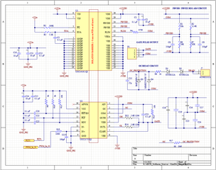
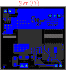
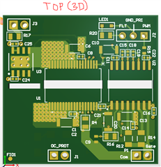
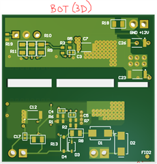
I have designed and built a prototype board for a gate driver circuit using a SiC MOSFET power module. The gate driver in use is the UCC21755-Q1, powered by the UCC14141-Q1 isolated DC-DC module.
I have a few questions regarding the circuit connections for the UCC14141-Q1:
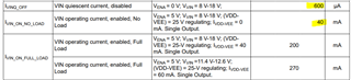
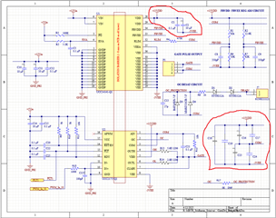
(1) FBVDD Pin Connection: Based on my schematic diagram (screenshot provided below), I want to confirm that the FBVDD pin should be connected to the midpoint of the resistor divider to generate 2.5V. To achieve 15VDD, I am using a 62k resistor on top and a 10k resistor on the bottom. For -3V on VEE, I am using a 12.4k resistor on top and a 62k resistor on the bottom of the second divider. Is this configuration correct?
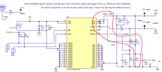
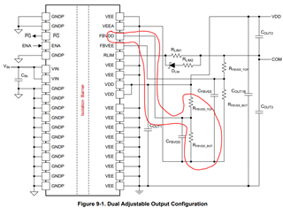
(2) Datasheet vs. EVM Schematic: On page 29 of the UCC14141 datasheet, for a dual output configuration, the FBVDD pin is connected only to the midpoint of the resistor divider. However, the schematic diagram of the UCC14141 EVM shows it connected to VDD as well. Which connection is correct? I have followed the datasheet instructions.
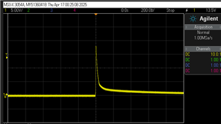
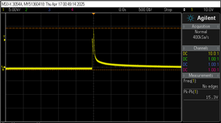
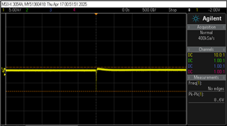
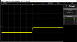
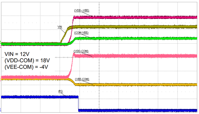
(3) No Output on VDD Pin: After supplying Vin=12V and V-EN=5V, there is no output on the VDD pin. I have verified the circuit multiple times and am confident there are no connection errors or mistakes. Is there something else I might be missing to activate the output?
Thank you for your assistance.
Best regards,
Sridharan