This thread has been locked.

If you have a related question, please click the "Ask a related question" button in the top right corner. The newly created question will be automatically linked to this question.

LM25180: Is LM25180 pin to pin replacement of LT8301? Will it work in the attached design

Part Number: LM25180
Other Parts Discussed in Thread: LM5181

Tool/software:

Hi Team,

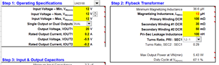
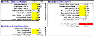
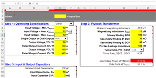
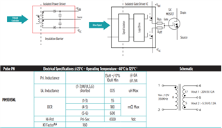
Is LM25180 pin to pin replacement for LT8301 ? Actually we are planning to use LM25180 instead of LT8301 in our existing project which will be used along with PM9595NLT to generate 20V and -5.5 as Power supply for SiC gate driver. PM9595NLT is having magnetizing inductance as Lm 13uH , minimum switching frequency as 280kHz and maximum switching frequency as 350 kHz. while the excel calculator is showing minimum magnetizing inductance required as 30uH. 

Can you confirm what will be the problem if Lm is 13uH?  And how to ensure switching frequency remains above 280 kHz?

PM9595NL datasheet - https://productfinder.pulseelectronics.com/api/open/product-attachments/datasheet/pm9595nl


Regards,

Ajit


  • Hi Ajit,

    I noticed you used LM5181 in your Calculator Tool but you should use LM25180 instead (LM25180 has higher power capabilities due to the x2 current rating od integrated MOSFET).

    -As you can see below, the tool recommends Lmag min of 36.6uH when using a 1.2:1 Nps turns ratio. For your load requirement, I recommend increasing Lmag with a new transformer. if you use a lower 13uH, the controller will switch from FFM mode to DCM (350kHz fsw) quickly and it will not work in BCM at all, which will decrease your efficiency at higher loads compared to using higher Lmag. 


    -Other option is to user a lower Nps 1:2 (similar to PM9595NLT transformer) which wilr educe Lmag min to 15.2uH but the problem is that the power will be limited. (3.71W pout max and you need ~5.1W).


    Thank you