This thread has been locked.

If you have a related question, please click the "Ask a related question" button in the top right corner. The newly created question will be automatically linked to this question.

BQ25756: BQ25756 not charging no switching issue

Part Number: BQ25756
Other Parts Discussed in Thread: BQ25750

Tool/software:

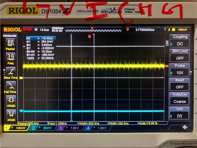
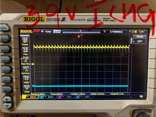
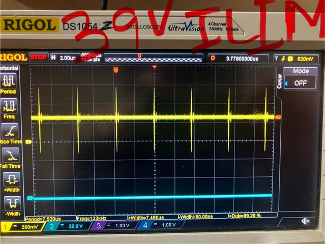
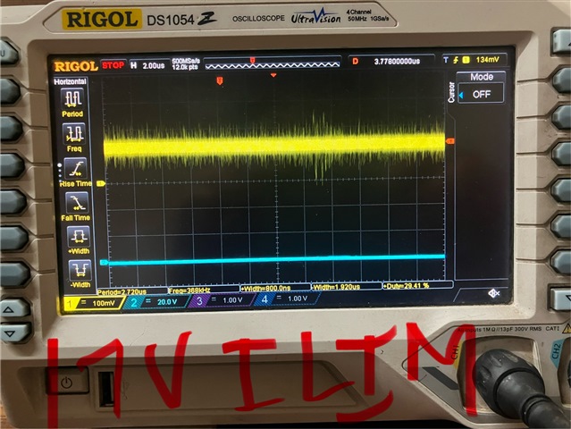
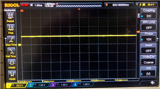
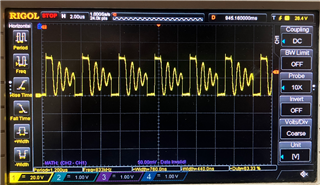
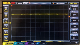
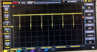
I have observed a strange issue. I had designed the charger to charge 38.5V 12S lifepo4 battery with charging current of about 10A. I connected the battery and input voltage was also about 45V , but it did not start charging , no switching waveform forms were observed. The drv_sup is provided externally (10V). Checking everything looks fine but it doesn’t charge. I have attached the schematics for your reference. I did the testing with only the charger components without the MCUs. All of tge 5 boards that were assembled are showing same issue. Please let me know the possible cause ASAP.PCB_S20ACCB2_REV_A.pdf

  • Hello Tenzing,

    Your schematic looks good. I can't find any obvious bugs with it. I have questions to help debug this:

    1. Can you send me the inductor datasheet?
    2. Can you measure the voltage at the CE pin to make sure CE is being pulled LOW?
    3. What's the voltage on REGN? Is REGN turning ON to 5V?

    4. Can you measure the voltage on VBAT?
    5. Can you very carefully measure the voltage on VFB? When measuring this voltage, I recommend powering off the charger and then attaching the measurement probes.

    Best Regards,
    Ethan Galloway

  • 1. The part number used is :IHDM1008BCEV100M30 and link for the datasheet: https://www.vishay.com/docs/34522/ihdm-1008bc-x0.pdf

    2. Yes the voltage at CE pin was 0V and is pulled down

    3. Yes REGN pin voltage was 5V when turned on

    4. Voltage at VBAT was 40.3V

    5. VFB was 1.50V

  • Hello Tenzing,

    Thanks for the new information. The inductor's DCR might be too low for the BQ25756. Can you try using an inductor with a higher DCR? Does an inductor with a DCR of around 10mΩ work for the circuit?

    Best Regards,
    Ethan Galloway

  • Hello Ethan,
    Thank you for pointing it out, by the way how does the DCR of the inductor affect the switching issue? I think DCR of an inductor mostly relates to heat losses and efficiency. I used the design calculator and it shows minimum of 2.6mohm. I will try with different inductor with higher DCR value and let you know.

  • hello ethan,

    i tried using higher DCR 7mohm inductor but still same issue.

  • Hello Tenzing,

    Thanks for the new test information. I have a few other debugging suggestions:

    • Can you measure the voltage on ACUV?
    • Is the power good signal being emitted?
    • Can you read the registers of the BQ25756 while VAC is powered?

    Best Regards,
    Ethan Galloway

  • Hello Ethan,

    #ACUV = 1.57V @43V input
    #ACOV = 0.78V
    #yes the PG line is also low.
    #All the registers had default values, and the EN_CHG bit was also set to 1(which is by default). Whereas I checked the status pins outputs when a fully charged battery was connected it showed STAT1= HiZ and STAT2 = LOW(i.e. STAT1 = OFF STAT2= ON) but the status pins output didnot change even when partially discharged battery was connected. And still the controller didnot start the charging process.

    Also I measured the voltages at the gates of the MOSFETs, the MOSFET Q3 in the schematic(low side buck FET ) had 10V but all other gates of the FETs were at 0V.

  • Hello Ethan,
    I did check the MOSFETs and found out that low side MOSFET Q4 (in the schematics) gate ,drain and source was completely shorted. What could be the reason behind this?

  • Hello Tenzing,

    Thanks for measuring this. You measured the MOSFET itself being damaged? I would need more information before I can say for sure.

    I have a few more questions to debug this:

    • Does the circuit work with Q4 replaced?
    • Can you measure the voltage from BTST1 to SW1? This will let us know if the BTST caps are charging.
    • Do you see any switching waveform on LODRV1, HIDRV1, or SW1 with an oscilloscope?

    Best Regards,
    Ethan Galloway

  • Hello Ethan,

    • When Q4 is replaced the and powered up the mosfet gets damaged instantly.
    • The voltage at BTST caps rises to about 9V approx but spikes were also observed exceeding 10V.
    • At initial phase switching was seen but for very short time and then the mosfet gets damaged. Also spikes at the drain of the mosfet Q4 exceeded 100V those spikes were also seen on the gate of the mosfet.
       
  • Hello Tenzing,

    Thanks for the new information. Q4 being damaged is kind of strange. With a 45V input and a 38.5V battery, the charger should be in buck mode and Q4 should be OFF.

    I have a few other questions to help us debug this:

    • Does using other switching FETs have an effect on the circuit's behavior?
    • Does the circuit work at an input voltage of only 15V or 30V?
    • Also, when Q4 was damaged the 2nd time, which inductor was installed in the board?
    • If you have captured any waveforms, can you send them to me?

    Best Regards,
    Ethan Galloway

  • Hello Ethan,
    Yes exactly but in my case I'm not sure what happened.

    • I replaced the previous mosfets with another one but still it didnot work, and now there is no voltage on REGN. I tried replacing the IC but still did not work. And the PG output was toggling. The voltage at ACUV and ACOV is fine and is within the window.
    • The inductor that I used was the same as in the schematics.
  • Hello Tenzing,

    Thanks for the information.

    The inductor that I used was the same as in the schematics.

    I recommend using the 7mΩ inductor or higher for these debugging tests. The BQ25756 has a DCR detection algorithm that runs on startup.

    I replaced the previous mosfets with another one but still it didnot work, and now there is no voltage on REGN. I tried replacing the IC but still did not work. And the PG output was toggling. The voltage at ACUV and ACOV is fine and is within the window.

    Can you still talk to the IC over I2C?

    Also, you are probably already doing this for these debugging tests, but I recommend using CV load and setting the current limits on the input supply low. Also, it might be safer to set the charge current to 1A or 2A for the initial tests as well.

    Best Regards,
    Ethan Galloway

  • Hello Ethan,
    It was a different issue rather than the DCR algorithm kicking in, the series filter resistor(10ohms) at the input and output current sense resistors were completely open which caused the input to stay at high impedance picking up stray voltages and that triggered the OCP which stopped the charging process. But I could not find out how those resistors blew open? This is the same PCB that I used before , the one with the damaged MOSFETs.

    Yes the MCU did communicate over I2C, there was no issue even when there was not 5V at REGN. But I still could not understand how the series resistors blew open.

    After that I replaced all four series 10ohm resistors and reduced the input current to 4A and output current to 2A and disabled PFM. It started charging the battery. 

    But when in boost mode the charging current reduced to about 0.2A (I/P volts: 18-37V) and never rose up even though the IC was in CC mode(charger status register value). And when the input voltage was increased to 39V then current rose up upto 1.5A but again at 40-44V input the current dropped. I also trioed enabling PFM but same result, no change.

    I also added the RC filters at the ILIMz and the ICHG pins as per the EVM but still nothing changed, the only thing that changed was the waveform was much cleaner at those pins than before, but not as clean as it should be. 

    Could this be the reason behind the strange behaviour? Or should I make more changes to the hardware or are there something that I'm missing, please suggest.

    I also tried enabling MPPT niether the curent value changed nor the MPPT is working. MPPT parameters were in default setting.

  • here are the scope shots at ichg pin and ilim pins measured at 17V and 39V inputs

  • Hello Tenzing,

    Thanks for the new information. That's a very good find with checking the 10Ω current sense filter resistors. We are swamped at the moment so I'll take a more in-depth look at this later this week.

    In the meantime, I have a few test suggestions:

    • Can you set ICHG_REG to your charge current and then set EN_ICHG_PIN=0? This will make the IC ignore the ICHG pin and only using the ICHG register. Does this change the IC's behavior?

    • Can you do the same test for ILIM_HIZ by setting EN_ILIM_HIZ_PIN=0?

    • After doing the above two tests, can you see if the BQ25750s charge current is related to the VIN/VBAT ratio and not the register settings?

    • Can you try installing a new BQ25750 IC on the board?

    Best Regards,
    Ethan Galloway

  • Hello Ethan,

    I checked disabling ILIMZ and ICHG pin via the register and current limit values of  both the registers are set to default. but still same issue. the charge current does not go above 1A. The IC is a new one, by the way you meant BQ25756 not BQ25750 right? 
    And what do you mean by VIN/VBAT ratio? Is there any issues when working with  higher voltage batteries? Or is there any hardware issues that might have caused such problems in charging the batteries? Please help us find out ASAP or we shall switch to different controller.

  • Hello Tenzing,

    Thanks for being patient with this and thanks for doing these tests.

    by the way you meant BQ25756 not BQ25750 right? 

    Yes, I meant to say the BQ25756.

    And what do you mean by VIN/VBAT ratio? Is there any issues when working with  higher voltage batteries?

    The BQ25756 does not have issues with higher voltage batteries. Because the register settings wouldn't adjust the charge current, I was curious if changing the VAC or VBAT voltage would adjust the charge current.

    Or is there any hardware issues that might have caused such problems in charging the batteries?

    The BQ25756 IC by itself doesn't have any hardware issues that prevent it from charging batteries.

    I think the IC might be have been damaged by previous tests. Can you do a few more tests?

    • Can you send me an image of the SW1, SW2, and battery current waveform?
    • Also, can you read the status and flag registers to make sure the IC isn't in VAC_DPM mode or IAC_DPM mode?
    • You can also check if the IC isn't limited by hardware by measuring the ACUV pin or the ACOV pin.
    • If the SW1 and SW2 waveforms are not right and the IC doesn't have any input voltage issues, can you replace the IC?

    Best Regards,
    Ethan Galloway

  • Hello Ethan,

    Thanks for the test suggestions. By the way I didn't mean issue with the IC but I meant with my hardware. Anyways I have sent you the waveforms please have a look.
    The status register shows its in constant current mode and no flags are set. Still the charging current doesn't seems to increase. I checked the waveforms after and before replacing the IC but still its the same. The waveform snapshots are after changing the IC , its the same as before replacing the IC. I don't know maybe I'm missing something.

    SW1 at input17V current draw was about 0.2A

    SW2 at input 17V current draw 0.2A

    SW1 at input 38V current draw 1.2A

    SW2 at input 38V current draw 1.2A

    SW1(yellow) and SW2 (blue) at input 45V current draw 0.2A

    The measured current is at the input. The current limit was set to 2A at the dc power source but on the board it was set to 10A via ILIMz , and the ICHG was set to 5A.

  • Hello Tenzing,

    Thanks for the new information. The waveforms look like normal operation.

    Can you send me your layout so I can review it?

    Also, can you measure the resistance of the ACN/ACP and SRN/SRP filter resistors just to be sure that these resistances haven't changed?

    current limit was set to 2A at the dc power source

    Can you tell me why you set the DC power source's current so low?

    Best Regards,
    Ethan Galloway

  • Hello Ethan,
    Yes also cross checked the waveform with the ones in the datasheet , it looks similar but is the waveform at the SW2 @17V normal waveform beacuse I see some ringing.

    Yes the filter resistor shows 10 ohms when measured, I guess its not damaged like before.

    I set the limit to 2A just t for the MOSFETs(p/n: STF13N60M2) to be on the safe side that I used now for the testing, because the MOSFETs have drain current of around 11A only.

    I also tried increasing the current limit of the source to about 10A but still nothing happened, the current draw remained the same.

    Please have a look at the layouts as per your request. Is there any issues with the layout and my components? it would be a great learning point to know about any issues, please suggest.

    Top layer

    Mid layer 1

    mid layer 2

    bottom layer

  • Hello Tenzing,

    Thanks for the new information. I quickly looked the layout and I can't find any problems with it.

    I've been reading through the FET datasheet. Can you try using different FETs in the circuit?

    I found that the reverse recovery time of the FETs in the circuit are very large.

    Also, are you still using a 10V external gate drive or are you using the 5V gate drive voltage from REGN? The FETs you are using will need an external gate drive voltage to operate effectively because the threshold voltage can vary between 2V and 4V.

    If you can find FETs available, I'd recommend trying FETs that are similar to the SiR680LDP.

    Let me know if you have any questions about this.

    Best Regards,
    Ethan Galloway

  • Hello Ethan,
    Thankyou for the suggestion and for point out about the reverse recovery time of the MOSFETs. Is this the reason behind the MOSFETs getting damaged in my initial tests? 

    yes we are using external 10V for the for the gate drive.

    And for the reverse recovery time of the FETs can you let me know the range or min/max reverse recovery time. Also can you recommend what other parameters should I look for when selecting the FETs and the Inductor as well.  

  • Hello Tenzing,

    Thanks for the clarification on the gate drive voltage.

    Is this the reason behind the MOSFETs getting damaged in my initial tests? 

    I'm not sure yet. I've never worked with FETs with a reverse discharge time this high before. Most of the FETs I've worked for the BQ25756 have a reverse recovery time of less than 50ns.

    And for the reverse recovery time of the FETs can you let me know the range or min/max reverse recovery time. Also can you recommend what other parameters should I look for when selecting the FETs and the Inductor as well.  

    The reverse recovery time will depend on the switching frequency. In general, you'll want a reverse recovery time as low as possible because the reverse recovery contributes to the switching losses. The need for a smaller reverse recovery time increases as the switching frequency increases.

    In general, here's a quick reference for the types of FETs I've used:

    For 250kHz, I've used FETs with a 35ns reverse recovery time.

    For 450kHz, I've used FETs with a 28ns reverse recovery time.

    For 600kHz, I've used FETs with a 11ns reverse recovery time.

    For the inductor, I recommend using an inductor with a DCR greater than 2mOhm. The inductance needed will heavily depend on the switching frequency.

    Let me know if you have any questions about this.

    Also, let me know if replacing the FETs works for your system.

    Best Regards,
    Ethan Galloway

  • Hello Ethan,

    Thankyou very much for the recommendations.

    I will change the FETs similar to the EVM and test it , and will let you know the results.

  • Hello Tenzing,

    Your welcome. Let me know what the results are of your test.

    Best Regards,
    Ethan Galloway