This thread has been locked.

If you have a related question, please click the "Ask a related question" button in the top right corner. The newly created question will be automatically linked to this question.

LM70880-Q1: Fly-buck with this converter?

Part Number: LM70880-Q1
Other Parts Discussed in Thread: LM70880, , LM5161, LM5169, LM5185, LM25185, UCC28C42

Tool/software:

Hi, 

I'm wondering if it is possible to implement a fly-buck with a converter like this with larger output currents(7-10A) and output voltages between 24-28V with a 28V input voltage.

I want the better EMI performance of a cuk/fly-buck and isolation at a little bit higher power output, but don't know what would be the best topology to achieve this.

Thanks,

Matt

  • Hi Matthew,

    I think it is possible. See the app note shown below:

    https://www.ti.com/lit/an/snva790a/snva790a.pdf

    Ben

  • Hi Matthew,

    Are there any further questions regarding this thread? If not, please close the thread by clicking on "resolved". Thanks,

    Ben

  • Hi Ben,

    I briefly went through SNVA790A. 

    Using a fly-buck  for this design with the app. notes suggested maximum 50% duty cycle. 

    Picking some close fit transformer from Wurth will get me a part with L1 = 100uH and a 2.8 turns ratio.

    ->  .32*(28V) = 8.9V = Vout1.

    Assuming Vf = 1V.

    If I want Vout2 =  24V,

    -> (24V+1V)/9v = N2/N1 = 2.8

    VL1 = 28V-9V =17V

    VL2 = 9V  X (2.8) =  25.2v 

    VD = 24V + (2.8)x(28V - 9V) = 77.2V

    VL1 = -9V

    delta IM = [(28V - 9v)x.32]/(100uH*700Khz) = 87mA

    Iout1= 100mA

    Iout2 = 7A

    Ipri pospk = 100mA +[(2.8)x7A] +(43.5mA) =  19.744A

    Ipri_negpk = -[2.8x7Ax(2x.32/.68)] -43.5mA +100mA = -18.38A

    At this point, I don't see any available transformers for PCB applications that have current ratings for a load current of 7A . The I sat is always much lower and I out on each side of the transformer at these voltages isn't available. 

    Firstly, I think I could use some background on if it is possible and how to pick/design a transformer for an application like mine.

    Clarifications on misunderstandings I have with how I approached the beginning of a fly-buck design.

    Or maybe a suggestion for a more suitable topology for an isolated 7A 24V output supply.

    Thanks,

    Matt

  • Hi Matt,

    Have you looked into a flyback topology? The power requirements that you need to meet for your isolation is difficult to achieve with a PCB mounted transformer.

    Ben  

  • Don't flybacks use a transformer as well?  Would I have an easier time finding a transformer for a flyback?   I was avoiding it because I thought it might be too noisy and one of my requirements is EMI performance. 

    Cuk topology was also suggested, but I'm not sure where I'd start in that case.

  • Is the goal to meet a specific EMI standard (i.e. CISPR 11/22)? Are you concern about conductive or radiated EMI? Adding an input filter for VIN will help with EMI.

  • The goal is 461. Both. I would add the input filter, but the idea of testing the spread spectrum function of the IC on the LM70880 was interesting. 

  • There are conductive EMI plots in the LM70880 and LM706A0 EVM user guides.

  • Thank you that is awesome, but what I'm not sure about is if I can take an IC like this and implement it in a design that isolates the output. That is why I was pursuing the fly-buck.

  • Hi Matthew,

    I have added a colleague of mine who is more familiar with fly-bucks and isolated designs. Good luck to you!

    Ben

  • Hi Matthew,

    The LM70800-Q1 can support a fly-buck design, but unfortunately it may not be a right choice for your application, for the following reasons:

    • Your load current is 7 to 10A @24 to 28Vout.  As you have noticed from Harrison's article, for your 28Vin, you must use a coupled inductor with turns ratio at least 1:2. This means the equivalent primary load current would be 2x (7 to 10A), that is well beyond the LM70880-Q1's rating of 8A.  If you choose 1:2.8, the situation is worse.  
    • Since all your load are on the secondary side, and the fly-buck primary side just serves as a intermediate voltage rail for output cross-regulation, there will be a large negative current on the primary side, and it can trigger the IC's negative current limit to interrupt the power transfer during the off time of the main switch. See below snapshot of the datasheet ec-table.
    • If you compare with our devices labeled as fly-buck devices, like the LM5161, LM5169, etc, you can find the negative current limit, or the sink current limit as called in some datasheets, is usually ~2x of the positive current limit. 

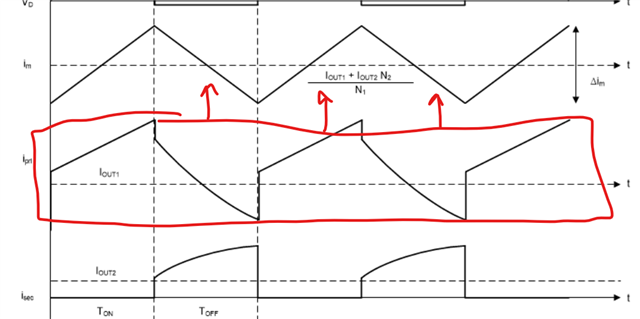
    Now, you may ask when the LM70880-Q1 can be used as a fly-buck?  I think the suitable application would be (1) the total equivalent primary load current should not exceeding the IC capability (i.e. 4/6/8A), and (2) the majority of the load is on the primary side, and a smaller load is on the secondary side, as depicted in the below graph from Harrison's article:  the higher the primary side load, the further way the negative peak from the negative current limit.  Of course, you also need to be sure your input voltage has margin for fly-buck, namely the min Vin should be at least 2x the primary Vout.  

    Hope this clarifies.

    Best Regards,

    Youhao

  • Hello Youhao,

    Thank you for all of that information. It helped me understand the fly-buck design better.

    Part of my question is , since the fly-buck won't work, are there any ICs you'd recommend for a flyback design that utilize a spread spectrum/good EMI performance?

    This would be chip specific, assuming that I will be adding an input filter as well. 

    Thank you,

    Matt

  • Hi Matthew,

    Our group used to have LM5185 PSR flyback but your >150W may stretch too much of a PSR flyback, and it does not have spread spectrum.  TI has an isolated power group but sorry I am not very familiar with their portfolios. Let me forward this e2e thread to them, and see if they can have a good solution for you.  

    Just note that tomorrow is a holiday, so you may get reply from them in next week.

    Best Regards,

    Youhao

  • The LM5185 might be solid for the lower power version of this design which is ~100W. But for a 150W design, I'm still not sure how to proceed.

  • Hi Matthew,

    Like said, I have forwarded your post to our isolated power experts in another group. You should receive reply next week.

    Thanks,

    Youhao

  • Hi Matthew, I'm sorry but we don't have a good match with any of our isolated bias supplies (typically <100W). 

  • Hi Ray,

    Do you have anything at 90-100W?

  • Probably closer to 50W for your Input/Output parms using something like the LM25185.

    At these higher powers, you may need to go with a PWM controller with an external FET such as the UCC28C5Y  . I know you were trying to avoid an external FET, but you can use techniques such as TVS damping and a gate-drive resistor to slow the edges. It all depends on what is considered "low EMI" for your system. Here's a reference design using an earlier version (UCC28C42) that you may find useful: https://www.ti.com/tool/PMP30720

    Regards,

    Ray