This thread has been locked.

If you have a related question, please click the "Ask a related question" button in the top right corner. The newly created question will be automatically linked to this question.

LM5156: LM5156: Boost converter 45V to 142V with LM5156

Part Number: LM5156

Tool/software:

Hi,

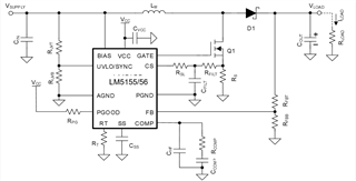
I'm trying to design a boost converter (it's my first time with BOOST converter) to have 142VDC in the output from 45VDC (regulated) in the input, so I was thinking on using the switching controller LM5156.

For this purpose, I used the Excel file for select the passive components and to reach this voltage (see picture below).

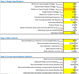
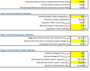
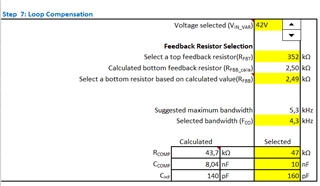
Based on the parameters set above I would need help to define the following components:

  1. Characteristics of N Mosfet Q1 -> I used WEBENCH but suggests IDEAL FET with VdsMax= 500.0 V and IdsMax= 100.0 Amps -> I think something with lower characteristics is sufficient, for example VdsMax= 200.0 V and IdsMax= 2.0 Amps -> Could you confirm? If so, do you have a PN to suggest?
  2. Characteristics of DIODE Shotcky D1 -> I used WEBENCH but suggests CUSTOM DIODE with VF@Io= 500.0 mV VRRM= 213.0 V -> I have not found any shotcky diodes with VRRM greater than 213V and with VF equal to 500mV. Can you confirm the need to use shotcky diodes with 500mV? What happens if I use a shotcky diode with higher VF? If so, do you have a PN to suggest?
  3. In order to to have 142V output I must use the set of two resistors on rfbt. Could be a problem?
  4. The inductor chosen is SRP2313AA-680M. Could you confirm that it’s okay or suggest an alternative?
  5. Are there any special precautions in choosing the size of the passive components?

Thank you and regards.

  • Hi Andrea,

    Thanks for using the E2E forum.

    1. I would recommend to use the FET with 2* the output voltage of the converter. The Ids should be 2* the peak inductor current of the converter. In your case Ids should be greater than 2 * 4.42 A.

    2. Using the diode with higher forward voltage drop will cause the higher losses in the diode and impact the efficiency of the converter, but the output voltage will still be regulated. 

    3. It is not a problem until unless the total resistance is same as of the calculation.

    4. The selected inductor is fine to me.

    5. I would recommend to use 0603 size or smaller

    I recommend to use mouser or Digi key filters to find the parts. 

    Best Regards,

    Hassan 

  • Hi Hassan,

    Thank you very much for your reply.

    I followed your advice to use Mouser for component selection.

    I selected the FET IPB60R060C7ATMA1 because it was compliant with the minimum characteristics highlighted by you and because it was the one with the lowest RdsOn (among the search results).

    Analyzing the datasheet of LM5156 there is a unclear part (see screenshot below):

    With the chosen FET should be compliant with the required equation because Qg=68nC and fsw=440kHz -> The result is lower than 35mA but I have a doubt about the selected FET’s Vgsth (see screenshot below):

    Could I have problems during the start-up since to be sure that the FET is closed I should have a voltage on the GATE pin greater than 6V? 

    Can the problem be solved using the UVLO function?

    Thank you very much in advance for the answer

    Best Regards,

    Andrea

  • Hi Andrea,

     As you have a constant supply voltage which is greater than the VCC threshold and the miller plateau is below the VCC voltage threshold. The selected FET is fine with the gate voltage and start up condition.

    Although this FET fulfil the requirement in datasheet, but still the Rd,on and gate charge for this FET is high, which will result into high FET losses and would impact the efficiency.

    I would recommend to set a filter again because there are still good options. For instance, (FYI) these FETs are match better than what you have selected. You can still search for even better options.

    https://www.mouser.de/ProductDetail/Toshiba/TPH5200FNHL1Q?qs=Ey7%2FXF42M3fNxTe44RMpaw%3D%3D

    https://www.mouser.de/ProductDetail/Infineon-Technologies/BSC320N20NS3-G?qs=mzcOS1kGbgfxde0AMdEAsw%3D%3D

    Best Regards,

    Hassan