This thread has been locked.

If you have a related question, please click the "Ask a related question" button in the top right corner. The newly created question will be automatically linked to this question.

LM51772: Same issues as another user with LM51772.

Part Number: LM51772

Tool/software:

I have the same issue as the user who posted this:

https://e2e.ti.com/support/power-management-group/power-management/f/power-management-forum/1440917/lm51772-lm51772rhar?tisearch=e2e-sitesearch&keymatch=LM51772#

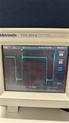
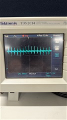
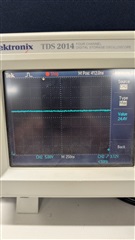
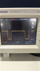
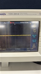
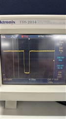
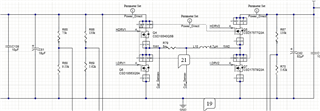
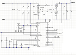
My schematic is almost EXACTLY the same as his but I am having the same issue. I am seeing the same behavior where if the voltage is below 16.8V it will boost regulate to 16.8V on the output. Then it will track VIN from 16.8V up to 24V. Above 24V it will buck regulate down to 24V. My external feedback is set to regulate to 24V. Can you help me diagnose this issue? I have been configuring and reading registers and have had no luck in solving this problem.

  • HI David,

    so I assume you have already checked that nRST is not floating -right?

    Can you share your schematic.

    Also some scope plots of  (when VIN > VOUT):

    • SW1 and SW2
    • FB and COMP
    • SS
    • VIN and VOUT

    Best regards,

     Stefan

  • I am not able to share the schematic. nRST is pulled up to VIN through a 10K. Below are scope captures of signals requested with Vin at 26V and Vout at 24V.

    SW1


    SW2

    VComp

    Vfb

    Vin

    Vout

  • HI David,

    thanks for the scope plots.

    Can you also provide the plots for the failing not working case. (Sorry missed that request yesterday)

    One thing which I could see in the plots it that you have a large undershoot on the switch nodes. This could be due the the probing not done well (e.g. due to a large ground loop by just using the ground clip). I you should check this again to not violate the abs max ratings.

    Best regards,

     Stefan

  • Below are the screen captures for when Vin < Vout_target:

    SW1

    SW2 (not switching)

    Vcomp

    Vfb

    I did look at SW1 (the highest voltage from previous pictures) with a smaller ground loop and verified that the voltage doesn't exceed the FET's rating of 60V when Vout > Vin (Vout is 26V):

    Here is the power path portion of the schematic that I can share:

  • Hi Davin,

    can you show a few ore cycles on to confirm that the signals are stable and do not jitter.

    Please also confirm that all other signals are stable when observed for a longer time (some ms).

    How do you have connected the current sense resistor? Do you use a Kelvin connection? Do you have the required Filter?

    Do you also use the average current limiter?

    Note: With the abs max ratings I esp. mean the LM51772

    Best regards,

     Stefan

  • They are VERY stable over hundreds of ms. The switch times are constant, the compensation and feedback are steady, and the output is well regulated. 

    I do not have the current sense filter at the moment. I had a 10 ohm series resistor, and yes with a Thevenin connection, and a 180pF cap. My switching frequency is ~625KHz (Rt is 51K). However, there was a screw up on the BOM and 10Ks were placed instead of 10 ohms so I removed them and the 180pF filter cap. However, when this bad filter was in place before it still regulated to the same setpoint, but it was just VERY erratic.  I have also changed the Vout register value to see if somehow it was latching the mode for the internal feedback network but that didn't change the output so I am fairly sure that isn't what is happening. 

    I am unsure of the use of the current limiter. I believe it is disabled but I can verify that tomorrow. 

    I also have verified that at no point am I getting close to going below the minimum on time of the switches for either mode, until I have 33V+ in, which I only designed it for up to 28V max input. 

    As for the LM51772 ratings: I have gone through the absolute ratings table in section 5.1 of the datasheet and measured each one in each mode (buck/boost) I do not see, at any time, where any of these ratings are being violated. 

    It seems that the FB operating point for the feedback error amplifier is 0.7V when in boost mode and then the specified 1V.

    Hopefully the current limit is the issue, but I am not holding my breath. Any other ideas?


  • I have confirmed that the current limiter is disabled. The ILIMCOMP/ISET pin is connected to the VCC2 pin.

    I will add that I have read the registers and they are all the default values listed for each one. Every startup the status register has the VIN bit set (0x08). I clear it and it never comes back. Must be something happening on startup. But with it cleared there is no change in the regulation behavior. 

    I have also disconnected all devices from the output so there is no output load current and the regulation behavior doesn't change either.

  • Hi Davin,

    It is a bank holiday today. Please expect a reply by Tuesday.

    Best Regards,
    Feng

  • Hi Davin,

    thanks for confirming that the Current limiter is not active and therefore can not limit the output voltage.

    So I assume that the current sensing has issues and will trigger over current within the controller and which leads to the reduced output voltage.

    Another option would be stability issues on VCC and the BOOT voltages. Can you measure both and also provide the part number of the cap you have used on VCC2.

    Best regards,

     Stefan

  • I have decided to share the complete schematic of this regulator and just remove the other portions of circuits on the sheet. 

    *Notes about the schematic above:

        1) R243 and R244 are 10 ohms on the board, not 10k.

        2) R72 and R74 are not populated. 

        3) R77 is really a 0 ohm on the board.

    The cap used for VCC2 is CL31A226MOCLNNC. 

    VCC2 is at 5.00V and over 100ms of time on the scope seems very steady. Likewise for VCC1.

    The voltages at HB1 is at 17V and also seem very steady. HB2 is switching between 4V and 17V. This is all with the input voltage of 12V. Here is HB2:

    It seems fine to me. If there is anything else I can check I am more than happy. Also, Is there any way to rule in or out the current limit theory? 

  • I have found that if I disable PCM in register D9, instead of the bootstrapped setting of enabled at 30%. Replacing R76 on the schematic with a 0 ohm has it now booting up with 24V.