This thread has been locked.

If you have a related question, please click the "Ask a related question" button in the top right corner. The newly created question will be automatically linked to this question.

UCC21750-Q1: UCC21750 spice model D_D1 define

Part Number: UCC21750-Q1
Other Parts Discussed in Thread: UCC21750

Tool/software:

I am using the Spice model and converting it to a MAST file in Saber simulation. When I run the model, it always reports an error about d_d1 being out of range. So, I checked the model and found that the diode is defined in the model.


*$
.SUBCKT D_D1 1 2
D1 1 2 DD1
.MODEL DD1 D( IS=1e-15 TT=10p Rs=0.05 N=.1 )
.ENDS D_D1
*$*$
.SUBCKT D_D1 1 2
D1 1 2 DD1
.MODEL DD1 D( IS=1e-15 TT=10p Rs=0.05 N=.1 )
.ENDS D_D1
*$

I want to know if "N = .1" is a normal value?

Thanks

  • Hi Jiang,

    We do not support Saber simulation, and I am not sure about its compatibility with Spice. You can try deleting this diode subcircuit entirely. I have a different version of the UCC21750 Spice model that you could try instead also:2133.UCC21750.zip 

    Best regards,

    Sean

  • Hi Sean

    Thank you for providing the updated SPICE model.
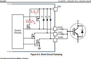
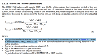
    After testing it, I noticed that the internal resistor at the "OUTH" pin is 2.5 Ω,
    whereas section 9.2.2.5 of the datasheet (Picture 2) specifies it should be 0.7 Ω,
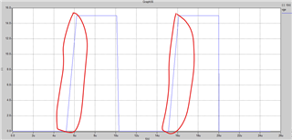
    which results in a slower rising time (as shown in Picture 3).

    As shown in Picture 1, it seems the internal N-MOS is not operating together with the P-MOS.

    Additionally, there is no current output from the "AIN" pin,
    and the "DESAT" pin is triggered when the DESAT current exceeds 500 µA,
    which is beyond the value specified in the datasheet.

    I'm continuing to review my MAST model (converted from the SPICE model),
    but could you please help verify if the original SPICE model is correct?


    Thank you 
    Jiang

  • Hi Jiang,

    Thank you for your feedback. I have added a 200uA Iain current source. You can also add one externally to the previous model.

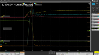
    The datasheet gives a 2.5 Ohm Routh value: I have found that this seems to be a more accurate representation of the device behavior. Here is a double pulse test with the UCC21750 and the C3M0015065D. The output sources Miller plateau current from <2V away from the positive rail, where the NMOS will be in pinch-off. For this reason, I did not include the NMOS in the model for improved simplicity and to aid simulation convergence.

    Best regards,

    Sean