This thread has been locked.

If you have a related question, please click the "Ask a related question" button in the top right corner. The newly created question will be automatically linked to this question.

TPS25751: Chip application problem

Part Number: TPS25751


Tool/software:

1. Can TPS25751 be applied to the following scenarios? When the ROUTER is a SINK, it needs to be powered by USB-PD at 12V-3A, and the ROUTER has no battery. When the ROUTER is a SOURCE, it has other external power supplies and needs to discharge 5V 0.5A externally. It supports external devices such as USB flash drives.
2. Can TPS25751 + EEPROM negotiate a power of 12V-3A or more independently with the charger when there is no main control working?
3. How to operate the EEPROM burning method? Is the software compilation and burning done by Ti or the customer? How to burn the software specifically?
4. Can the 3.3V power supply of TPS25751 directly use the 5V/12V power supply of VBUS without external power supply?
5. What is the relationship between VBUS_IN and VBUS?

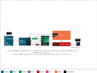
Please help answer our five questions based on this block diagram.

  • Hello,

    1. Can TPS25751 be applied to the following scenarios? When the ROUTER is a SINK, it needs to be powered by USB-PD at 12V-3A, and the ROUTER has no battery. When the ROUTER is a SOURCE, it has other external power supplies and needs to discharge 5V 0.5A externally. It supports external devices such as USB flash drives.

    What is the expected behavior if the charger connected only supports 5V or 9V?  Since there is no battery then this is outside of the expected use case, and there may be issues we have not addressed.

    2. Can TPS25751 + EEPROM negotiate a power of 12V-3A or more independently with the charger when there is no main control working?

    Yes.

    3. How to operate the EEPROM burning method? Is the software compilation and burning done by Ti or the customer? How to burn the software specifically?

    The GUI tool creates the image.  You would need an EEPROM programmer to load the image to the EEPROM.  You can also use the PD to write to the EEPROM.

    4. Can the 3.3V power supply of TPS25751 directly use the 5V/12V power supply of VBUS without external power supply?

    Yes there is an LDO built into the system.

    https://www.ti.com/lit/ds/symlink/tps25751.pdf#page=30

    5. What is the relationship between VBUS_IN and VBUS?

    VBUS_IN is the input and VBUS is the output of the PP5V.  Electrically these should be connected.

    Regards,
    Chris

  • 4. Can the 3.3V power supply of TPS25751 directly use the 5V/12V power supply of VBUS without external power supply?

    Yes there is an LDO built into the system.

    ---Biot.Chen say :when TPS25751 is the source(host),there is a external power supply  to PP5V, At the same time, is it necessary to provide external power supply for VIN3V3? 

  • 3. How to operate the EEPROM burning method? Is the software compilation and burning done by Ti or the customer? How to burn the software specifically?

    The GUI tool creates the image.  You would need an EEPROM programmer to load the image to the EEPROM.  You can also use the PD to write to the EEPROM.

    ---Biot.Chen say: how about  using the PD to write to the EEPROM? can you provide a SOP documents for me  please,THX

  • My application scenario is that USB-C is a DRP port.

    When the PD CHARGER is inserted, the TPS25751 needs to apply to the PD CHARGER for a power of more than 30W(9v or 12v) (less than 30W will not respond). When the USB sink (USB flash drive) is inserted, TPS25751 needs to provide it with a power supply of 5V and 0.5A.

    May I ask how I should configure the Pull-up and pull-down voltage divider resistors of ADCIN1 and ADCIN2

  • We want to design the I2Ct interface as a pull-up 1.8v to communicate with the 1.8V I2C interface of the CPU. May I ask if this design is reasonable?

  • 1. Can TPS25751 be applied to the following scenarios? When the ROUTER is a SINK, it needs to be powered by USB-PD at 12V-3A, and the ROUTER has no battery. When the ROUTER is a SOURCE, it has other external power supplies and needs to discharge 5V 0.5A externally. It supports external devices such as USB flash drives.

    What is the expected behavior if the charger connected only supports 5V or 9V?  Since there is no battery then this is outside of the expected use case, and there may be issues we have not addressed.

    ---Biot.Chen say:we need 30w power supply for Router,so,if there is only 5v or 9v from charger,TPS25751 have to Keep the VBUS_IN to PPHV power path off until a 12V 3A charger appears

  • TI is closed today, sorry about delay in response. 

  • hello,can you update me  on above questions?

  • Hello,

    ---Biot.Chen say :when TPS25751 is the source(host),there is a external power supply  to PP5V, At the same time, is it necessary to provide external power supply for VIN3V3? 

    This will depend upon how you want the device to behave.  The PD remain off until either VIN_3V3 is applied or VBUS which is the dead battery use case.  The PD will be a sink only in the dead battery case.  If you want source behavior then VIN3V3 will need to be applied.

    Regards,

    Chris

  • Hello,

    ---Biot.Chen say: how about  using the PD to write to the EEPROM? can you provide a SOP documents for me  please,THX

    Please refer to these documents:

    https://www.ti.com/lit/pdf/slvafl1

    https://www.ti.com/lit/pdf/slvucr8

    Regards,
    Chris

  • Hello,

    When the PD CHARGER is inserted, the TPS25751 needs to apply to the PD CHARGER for a power of more than 30W(9v or 12v) (less than 30W will not respond).

    You can set the configuration and the power path to not close until the required power is provided.  Use the safemode.

    Regards,

    Chris

  • Hello,

    We want to design the I2Ct interface as a pull-up 1.8v to communicate with the 1.8V I2C interface of the CPU. May I ask if this design is reasonable?

    Yes.  It is not explicitly stated, however there are references to 1.8V in the I2C datasheet specification. 

    https://www.ti.com/lit/ds/symlink/tps25751.pdf#page=18

    Regards,
    Chris

  • Thank you for your reply and I have  another question please help me make out

    There are three pin about DRAIN(PIN15/30/40),they were floating in the reference design.we just copy the floating too,no any connection,is it ok ?

  • Could you provide a driver code base on Linux to us?

  • Hello,

    There are three pin about DRAIN(PIN15/30/40),they were floating in the reference design.we just copy the floating too,no any connection,is it ok ?

    Yes.  Please follow the layout guidelines in the datasheet.  

    www.ti.com/.../tps25751.pdf

    Could you provide a driver code base on Linux to us?

    We do not have any linux drivers.  

    https://e2e.ti.com/support/power-management-group/power-management/f/power-management-forum/1403165/tps25751-linux-mainline-support/5370715#5370715

    Regards,
    Chris

  • My application scenario is that USB-C is a DRP port on a Router.

    When the PD CHARGER is inserted, the TPS25751 needs to apply to the PD CHARGER for a power of more than 30W(9v or 12v) (less than 30W will not respond). When the USB sink (USB flash drive) is inserted, TPS25751 needs to provide it with a power supply of 5V and 0.5A.

    May I ask how I should configure the Pull-up and pull-down voltage divider resistors of ADCIN1 and ADCIN2

  • Hello,

    The PD needs to be configured in SAFE mode so that the sink path will not be automatically enabled upon first connection.

    Regards,
    Chris

  • so which number should i set the ADCIN1 as between 7 and 0 while ADCIN2 as 0?

  • Hello,

    I do not know.  It will depend upon which I2C address you want to use.

    Regards,

    Chris