This thread has been locked.

If you have a related question, please click the "Ask a related question" button in the top right corner. The newly created question will be automatically linked to this question.

LP8556: LP8556SQ-E08/NOPB schematics

Part Number: LP8556

Tool/software:

Hi team

We would like to use LP8556SQ-E08/NOPB for pure hardware test, no software engagement.
1. LP8556SQ-E08/NOPB is "PWM Only" without I2C master, could we directly pull pwm pin to high (VDD power domain), as 100% duty?
2.FSET resistor can be followed Table5 to changed the fsw, does Iset have similar table can be followed?
3.Our LED total current is 20mA, any suggest Iset resistor value?
3.VBOOST voltage is automatically detect and setup to 13.2V?
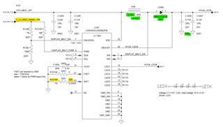
4.As below screenshot, anything need to be changed?
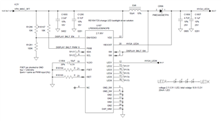
BR
Ethan

  • Hi Ethan,

    1. Yes PWM input can be configured as 100% duty. 

    2. For the LED current set per output, you can refer to Table 13 when ISET_EN=0 and Table 15 when ISET_EN=1.

    3. As the full scale ILED is 20mA, you can put an optional 24k RISET from ISET to GND.

    4. The initial boost voltage is configured with the VBOOST field. This field also sets the minimum boost voltage. The VBOOST_MAX field sets the maximum boost voltage. And yes you can also use the BOOST Adaptive Control to make Vboost adaptively change based on the need. For more details, you can refer to DS 8.3.1.3 Output Control.

    5. 

    1) EN/VDDIO pin voltage is recommended to be 1.62V-3.6V. In the schematic, with Vin=4.2V, EN/VDDIO pin voltage will be 3.8V which exceeds the recommended range.

    2) PWM signal is a digital logic pin and its high voltage level is recommended to be within the VDDIO. Please don't connect PWM pin directly to VIN. And it is recommended to use an external signal rather than VIN to feed to PWM pin.

    Regards,

    Hongjia

  • Hi Hongjia

    Thank you for the quick reply, I modify schematics as below.
    1. EN/VDDIOpul up power domain change to 1.8V.
    2. ISET change to 24K pull down.
    3. To reduce layout area,
        inductor change to 4.7uH, 0.41A (LSBHB1608KKT4R7M)
        schottky diode change to 30V, 100mA (RB521CM-30)
        output cap 4.7uF change to 0402 package 


    BR
    Ethan

  • Hi Hongjia

    Due to there is no pwm signals from SOC side, could we pull up 10K to 1.8V directly?

    BR
    Ethan 

  • Hi Ethan,

    Only 1 out of 6 LED channels is used, right? The saturation current of the inductor has to be higher than the IL_peak. If the total LED load is 13.2V, 20mA, it's OK to use the 4.7uH inductor with 0.41A current rating. 

    For the PWM signal, if you want a 100% duty cycle, I would recommend to pull it up to VDDIO/EN as its voltage level need to be within the digital power supply VDDIO.

    Regards,

    Hongjia