Other Parts Discussed in Thread: LMR51450,
Tool/software:
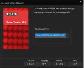
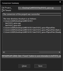
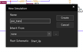
I am using PSPICE for TI to analyze the operation of the LMR51610.
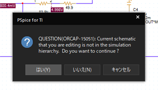
But I have some problems with this approach.
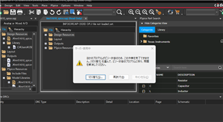
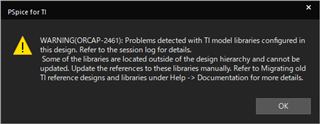
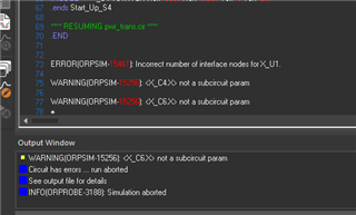
The first problem is that when i use the model data that is built into PSPICE, get the error message "ERROR(ORPSIM-15461): Incorrect number of interface nodes for X_U1."
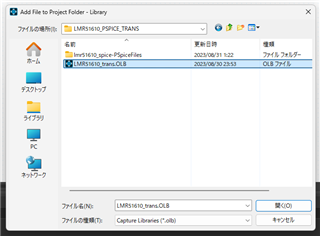
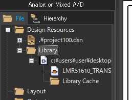
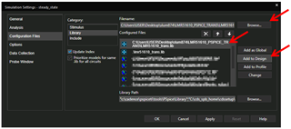
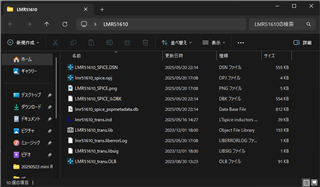
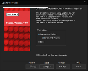
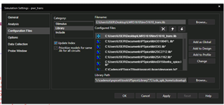
This problem can be solved by downloading and using the latest model data.
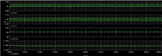
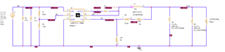
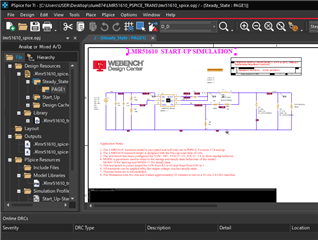
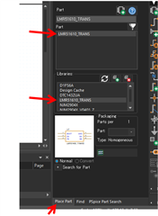
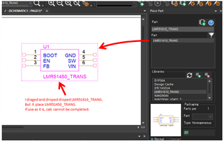
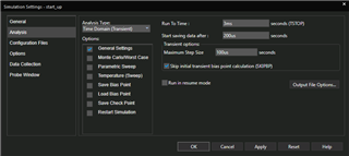
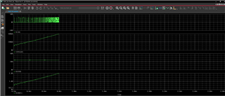
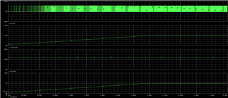
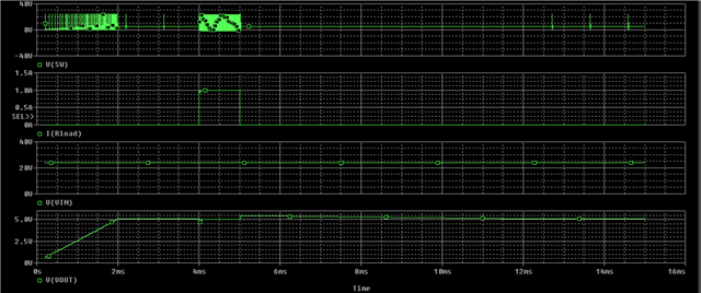
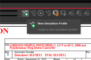
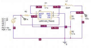
The second problem is that when i run PSIPCE on a simple circuit like the one below using the latest model data, PSPICE does not complete the calculation job even after a day. If i use the sample project included to the model data, PSPICE completes the calculation job in just a few minutes. When I use the model data into a circuit, the model data is displayed as LMR51450_TRANS. Is the inside of the model data normal?
The third problem is that LMR51610 has two switching frequencies, one is 400kHz and the other is 1.1MHz. How can I change the switching frequency in the model data?
thank you.