This thread has been locked.

If you have a related question, please click the "Ask a related question" button in the top right corner. The newly created question will be automatically linked to this question.

LM74502: LM74502 as High side driver in Back to Back connected common source Mosfet

Part Number: LM74502

Tool/software:

Dear TI Team, 

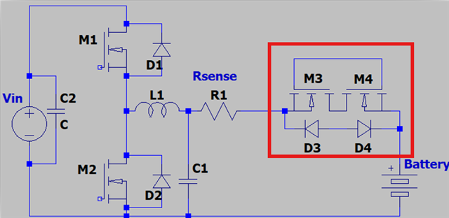
I am planning to place 'back to back connected N channel mosfet in common source configuration' at the output of the synchronous buck converter. I want to replace the output relay with this 'back to back connected Mosfet pair' which is used to cutoff & connect the circuit from the Load. Here, Load is the Battery cell.

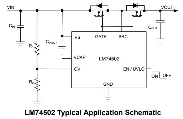
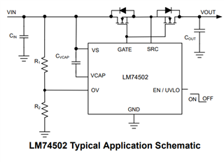
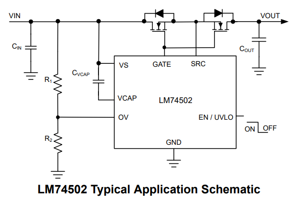
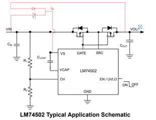
You can see attached image for reference. 

Also note that, these back to back Mosfet pair will be either continuously ON or continuously OFF (i.e. Similar to relay). And need to drive them on High side.

Specification of Mosfet for driving requirement is;
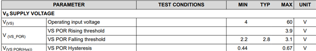
1. Vds- 10V

2. Rds(ON)- 3 mOhm

3. Qg total- 70 nC

4. Vgs max- 20 V

4. I max through this Mosfet- 10 A

Here, I wanted to know that the IC- LM74502DDFR is Suitable to keep Mosfet pair continuously ON or OFF??? Both mosfet Gate are common and Source are also common.

Please revert ASAP.

  • Hi C S,

    Yes, LM7502 will be able to drive these FETs.

    Sharing the application schematic for the same.

    Regards,

    Shiven Dhir

  • Can you also share simulation model or file if available. 

    Meanwhile also confirm if this LM74502 is capable to drive for continuous operation. As I am using this for replacing the relay in my circuit. 

    Also Ifyou have any application note for reference for the same ?

  • I have two main queries here,

    1. Will it allow to flow current in both direction?? i.e. Battery charge and discharge?? 

    2. Another question, In diagram, Vs is supplied via Bus voltage, but is it OK if I want to use other 12V supply which I have in my PCB??

    Kindly reply ASAP.

  • Hi C S,

    1. Simulation model is available in the product folder.

    2. Yes, controller can support continuous operation.

    3. Yes, it will allow bidirectional current once the controller is active and GATEs are high

    4. Using external voltage source can be risky as VCAP is driven at VS+(11V~12V) and GATE follows VCAP. There is a high chance of FET VGS violation in case of undershoot at power bus. It is better to connect VS to bus voltage

    Regards,

    Shiven Dhir

  • Understood Shiven, But My case is different. Let me explain more clearly.

    Actually, I am going to connect 'N- channel Back to back Mosfet pair' on My Syncronous buck converter Output. The LM74502 will Turn ON and Off the Back to back modfet to connect & disconnect the Buck converter output from the load. The converter is bidirectional so, Load also can supply back to converter, (Here converter work as Synchronous Boost). 

    Vout range- 1V to 6V 

    Iout~ 20 A

    Now, If I will connect the IC Vs pin to Converter Output, then it will work 11~12 V above that supply, I understand that. But what if Load will supply back to the grid, i.e. Need to connect Converter with Load when Converter output is Zero, because here Load will supply power to converter.

    So, I was thinking to just supply IC from external 5V. So it can Generate Vgs~ 5V+12V=~ 17V, i.e. 5V above the Vs.

    Now here How it will work I think:

    1. If my Vo of Converter(i.e. Back to back Mosfet input) ~ 3V 

    Then Vgs generated from IC ~ 17V and actual voltage on the Mosfet gate-source is- 17V-3V = 14V

    2. If my Vo of Converter(i.e. Back to back Mosfet input) ~ 6V 

    Then Vgs generated from IC ~ 17V and actual voltage on the Mosfet gate-source is- 17V-6V = 11V 

    3. If my Vo of Converter(i.e. Back to back Mosfet input) ~ 3V 

    Then Vgs generated from IC ~ 17V and actual voltage on the Mosfet gate-source is- 17V-3V = 14V

    My mosfet is capable to handle upto 20V so its in range only. 

    Is my approach Proper?? 

    And what if I need to give direct Bus voltage as IC input- i.e. as per below image- 

    It will surely work if direction id from Vin to Vout, but what when direction is reversed?? How IC will work if it is supplied from Vin side??That is main issue i am facing here. 

    Please reply ASAP. 

  • Hi C S,

    I understand that MOSFET rating is 20V VGS. But the controller has a limitation of 15V GATE to SRC rating.

    It is better to add a zener for robustness on GATE to SRC.

    If you want to power up bidirectionally.

    Regards,

    Shiven Dhir

  • Oh Thanks Shiven, I didnt check the absolute max ratring of IC, Sorry for that. 

    Now I understand the intension. 

    Here what I am getting is, IC will always try to give Output i.e. Vgs ~ 11 to 12V above the Vs pin, right??? If it exceeds 165V then, It will limited to 15V. i.e. If my converter output is 6V then IC will give max 15V, So I will get 15V-6V - i.e. 9V on Mosfet Vgs. 

    Am I right ???

  • Hi C S,

    Yes, VG will be driven to VS + 11~12V. It will not be limited to 15V. There is not VGS sensing mechanism.

    If your converter is at 6V, yes, VGS will be 9V.

    Regards,

    Shiven Dhir

  • Ok Shiven, 

    WIll it operate at Vs~1V ??

  • Dear Shiven, 

    My system Vout range is 0.5V to 6V. That's why I need to use external voltage source.

    I want to know which risk is associated if using external Voltage source, i.e. If I use external 5V as a IC voltage source, Then how much voltage on the Vgs Mosfet will see? if Bus voltage is 2 V at that time??

  • Hi C S,

    At VS = 1V, the controller will not work.

    VS rising PORR is 3.9V

    If you use 5V external signal, bus voltage 2V

    VCAP should be 5+12V. Hence GATE will be at 17V and VGS will be 15V. This at the border of abs-max rating.

    Regards,

    Shiven Dhir

  • Also if I dont OV protection, then Can I directly GND the Pin or it is better to GND it via 10K resistor ?

  • Hi C S,

    You can use a 10k resistor to GND.

    Regards,

    Shiven Dhir