Tool/software:
Hi team,
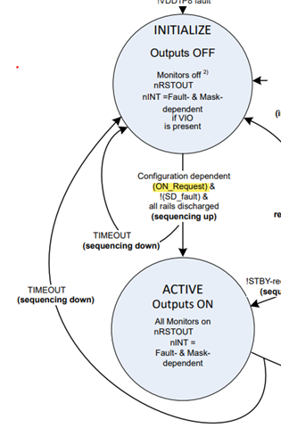
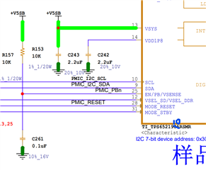
Pin 25 of TPS6521910 is PB by default. When my customer uses TPS6521910, there is no reserved button in the schematic diagram. How can they achieve power-on enable in this case?
BRs,
Rannie
Tool/software:
Hi team,
Pin 25 of TPS6521910 is PB by default. When my customer uses TPS6521910, there is no reserved button in the schematic diagram. How can they achieve power-on enable in this case?
BRs,
Rannie