


Tool/software:
Hi Experts,
Can you assist this query from customer reporting design for Sync Buck Converter with its specification listed below:
a) VIn = 16V
b) VOut = 4.2V
c) IOut = 3A
d) Fsw = 200KHz
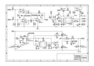
Fig 1: SCH of my Sync Buck Converter
However, I have measured some nodes and discovered some problems listed below:
Q1) Fsw is much less than that of my design Spec requirement

Fig. 2
From Fig. 2
- The Ringing seem exist at PWM and RT/CT Signal
- Design freq: 200k, but actual freq: about 85k
Q2: Current Sense Signal also suffers from Ringing

Fig. 3
From Fig. 3,
- Current Sense Signal also suffers from Ringing
However, VDD for U1 - U4 work normally at 12V.
Finally, the graphs below are PCB Top and PCB Bottom
Fig. 5: PCB Top
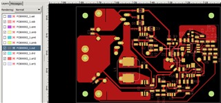
Fig. 6: PCB Bottom
How to solve issues Q1 and Q2? Thanks a lot.
Regards,
Archie A.
