Tool/software:
Hi, TI expert
The customer has a question about the circuit operation by applying LM5069-1.
The product uses a DC motor to drive the recliner sofa and is connected to a full bridge circuit.
The circuit design was made to protect the circuit in case of a short circuit in the motor.
- The product uses a 29V, 5.25A, DC adapter.
- The DC motor is driven in the recliner sofa and used for posture control (control is done using a Micom).
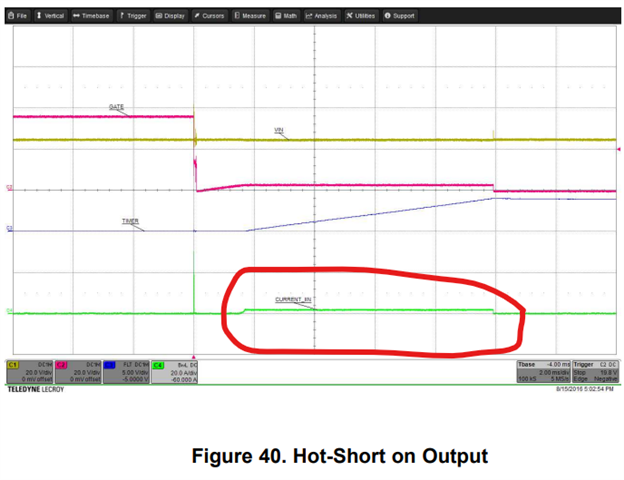
- The schematic is as follows.
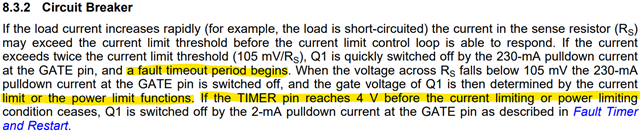
(Question)
Q1) When the circuit is configured and a faulty motor (short) is connected and operated, the protection circuit operates as shown in the waveform below, but I don't understand why the waveform below appears.
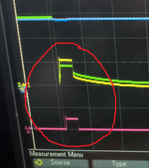
(Blue: DC_IN voltage, yellow FET gate voltage, green 29V voltage, purple current flowing through the FET)
The short circuit current flowed and the FET was cut off, but the voltage rose to about 10V again, and the current flowed for about 4msec and then turned off.
Q2) At first, when applying 1ea FET (DMN4010) to the circuit below and testing, the load was normal, the FET short-circuited in the faulty motor.
(Gate, drain, source all 0 ohm) So, when 2 FETs were connected in parallel, it worked normally. (Protection circuit worked normally)
I think the capacity of the FET is sufficient, but can you tell me why this phenomenon occurs?
(FET is DMN4010_Diodes)
Q3) Can you recommend another suitable FET for this? or is there another better solution?
Please check. Thank you.