A related question is a question created from another question. When the related question is created, it will be automatically linked to the original question.
If you have a related question, please click the "Ask a related question" button in the top right corner. The newly created question will be automatically linked to this question.
Subject: OTG Mode and Power Source Switching Issues with BQ25798
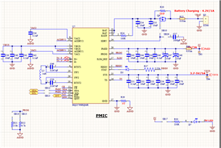
We are encountering an issue related to power source switching and OTG mode behavior with the BQ25798 charger IC. Our hardware configuration includes:
VAC2 (USB-C input) connected directly to the USB-C port.
VAC1 (Solar input) connected via a 5V buck converter output.
A Li-ion battery connected to the battery terminals.
We have configured the charger control register to enable both ACDRV1 and ACDRV2 when OTG mode is required. However, different input scenarios are yielding inconsistent behavior. Below are the detailed cases and the observed issues:
Case 1: USB-C (VAC2) Connected Initially
Setup: USB-C connected to VAC2, and battery connected.
Issue: The system operates normally while VAC2 is connected. Once VAC2 is removed and VAC1 is provided instead, enabling OTG causes the voltage at the PMID pin to drop to 0V. The battery also stops charging.
Case 2: Solar Input (VAC1) Connected Initially
Setup: Solar buck output connected to VAC1, and battery connected.
Issue: The system functions correctly with VAC1. However, if VAC1 is removed and VAC2 (USB-C) is connected instead, enabling OTG again results in PMID dropping to 0V, and the battery stops charging.
Case 3: Both VAC1 (Solar) and VAC2 (USB-C) Connected
Setup: Both solar and USB-C power sources are connected along with the battery.
Issue: When both power sources are connected, the device works fine. However, when both VAC1 and VAC2 are disconnected and only the battery remains, OTG mode fails to provide 5V on the PMID pin. The PMID remains at 0V. If only one of ACDRV1 or ACDRV2 was previously enabled (not both), the OTG function correctly boosts the battery voltage to 5V at PMID.
Request
We would appreciate guidance on:
Why enabling both ACDRV1 and ACDRV2 causes PMID to drop to 0V when only the battery is present.
The correct way to configure ACDRV1/2 and OTG mode to ensure reliable behavior across different power source transitions.
We would appreciate your guidance on the following:
How can we manage the OTG output so that it turns on from either ACDRV1 or ACDRV2 when the battery is connected? Our requirement is to allow users to connect either the USB-C input (on VAC2) or the solar input (on VAC1) — but only one at a time — to generate the 5V output on PMID and also charge the battery.
We want to ensure smooth switching between these two sources on an alternate basis while maintaining reliable 5V PMID output and charging.
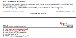
If I understand correctly, you want the charger to not charge when an input source is applied and sensed by VACx but, instead go into reverse mode and provide a 5V at PMID? The charger cannot both charge the battery and operate in the reverse/OTG to provide a voltage at PMID. If ACDRVx pins are not at GND, OTG cannot be enabled when VAC1 or VAC2 sense a voltage >UVLO. There is only a FET that turns on (or off for backup mode) between VBUS and PMID.
I recommend that you do not use the BQ25798 mux driver and external FETS. Instead, I recommend adding a TPS2121 or similar MUX IC with output connected to VBUS pin. The TPS2121 uses logic level inputs to determine which input is on.
As long as only one source is connected at a time, I see no issue.
This problem I see is the requirement for 5V at PMID. When USB-C is connected at VAC2, V(PMID)=5V. When solar panel connected at VAC1, V(PMID) = VOC*MPP%. When no source is connected at VACx, using backup mode (fast turn on OTG), V(PMID) can be regulated to 5V. I do not think this is what you want.
First, enabling both ACDRV1 and ACDRV2 is not allowed, ever. So I do not understand Case 3. If there are two valid inputs at VACx, VAC1 has priority. The host can I2C write EN_ACDRVx=0 and EN_ACDRVy=1. If the input on VACx goes below UVLO or triggers poor source, ACDRVy automatically turns on.
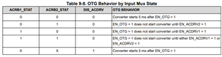
When MUX FETs are present, EN_OTG=1 only completes after one EN_ACDRVx is set to 1 per table below. But if you first set DIS_ACDRV=1 and then set EN_OTG=1, OTG will turn on.
This problem I see is the requirement for 5V at PMID. When USB-C is connected at VAC2, V(PMID)=5V. When solar panel connected at VAC1, V(PMID) = VOC*MPP%. When no source is connected at VACx, using backup mode (fast turn on OTG), V(PMID) can be regulated to 5V. I do not think this is what you want.
Actually, this is exactly what we want to implement.
Let me clarify our use case:
We have two power sources: USB-C on VAC2 and a solar panel on VAC1.
Only one source will be connected at a time, but occasionally both may be connected.
Our goal is for the system to:
Charge the battery from whichever input is available (VAC1 or VAC2).
Provide 5V on PMID during charging from either source.
Automatically switch to backup (OTG) mode, providing 5V on PMID from the battery when both inputs are disconnected.
We’ve observed that enabling both ACDRVs allows us to operate on either input individually and even when both are present. However, once both inputs are unplugged, the IC does not enter backup mode to maintain 5V on PMID using the battery — which is what we are trying to achieve.
Could you please guide us on how to correctly configure the BQ25798 to enter backup mode and provide 5V from the battery when VAC1 and VAC2 are not present?
Your guidance on this final piece would be greatly appreciated.
Regarding 2 above, when solar panel is attached, V(PMID) = VOC*MPP% which may not be 5V.
Regarding backup mode, it is designed to auto turn on (assuming EN_BACKUP bit=1) when there is no voltage on VAC2 and VAC1 voltage source is removed. In other words, only VAC1 supports transitioning back from backup mode without dropping PMID. When BQ25798 transitions from backup mode to VAC2, PMID drops to GND for a brief period of time. The following sequence is used to transition the source which powers the PMID load from the battery to the VAC2 source while optionally re-arming the backup mode:
1. Set EN_BACKUP = 0.
2. Set DIS_BOTH_ACDRV = 0
3. Set EN_ACDRV2 = 1
4. Determine the source at VAC2 is valid (is not in overvoltage and did not fail poor source detection) by reading back EN_ACDRV2 as 1.
5. Set EN_OTG = 0, in order to exit OTG mode and enter the forward charging mode without PMID voltage crash.
6. (Optional) Set EN_BACKUP to 1 to rearm backup mode.
Thank you again for your detailed response — it has been very helpful.
I still have a few clarifications regarding our use case and implementation goals:
Note: For VAC1, we’ve connected a solar panel to a 5V buck converter, and the buck output is supplied to VAC1 at 5V. In this setup, we believe MPPT functionality may not be necessary.
How should the device operate when both inputs are connected — 5V solar (via buck) at VAC1 and 5V USB-C at VAC2? Based on the datasheet, VAC1 has priority over VAC2. We’d like to confirm that battery charging and system power at PMID remain stable in this scenario. Is any special configuration required to ensure reliable and predictable behavior?
How should the device behave when both VAC1 and VAC2 inputs are disconnected, but the battery is present? In this case, we would like the PMID rail to be powered from the battery — using backup or OTG mode — to maintain 5V output. Could you please confirm the recommended register settings or sequence to enable this behavior?
How should the device operate when only one input is connected (either USB-C at VAC2 or solar@5V at VAC1)? We would like the device to charge the battery and provide system power seamlessly from whichever source is connected, without requiring manual switching.
Additional Note: We are triggering the 5V output on PMID during the device's operation — turning it ON when needed and OFF when not required. Kindly confirm if there are any additional precautions we need to take in this case.
We appreciate your continued support and look forward to your suggestions on implementing this reliably.
Regarding 1, unless the buck converter has its own MPPT, it will likely crash the panel or the charger will crash the buck which will crash the panel at some point. You can try setting the chargers VINDPM slightly under buck converter output voltage and its IINDPM low to prevent the crash.
Regarding 2, To keep a voltage on PMID when using VAC1, I recommend EN_BACKUP =1 for back up mode. Backup mode must be reset after charging restarts. But as I mention above, there will be a delay when backing up from VAC2.
Regarding 3, the charger auto switches to the source that is available but there is a 250ms start up delay each switchover.
If in forward/charge mode, PMID cannot be turned off. If in OTG/reverse, the host can turn off OTG with EN_OTG bit.
I have one question regarding VACx threshold settings.
I would like to configure a voltage threshold for the VACx inputs so that I can monitor their status. Specifically, if the VACx input voltage drops below this threshold, I want to automatically enable OTG mode to supply 5V on the PMID pin from the battery.
I reviewed the datasheet but couldn’t find any specific register or configuration for setting a custom VACx threshold. Could you please advise if there is a way to define or monitor such a threshold, or how best to implement this type of condition?
That is what backup mode is for VAC1 only. There is no automated way to do this for VAC2. Even with backup mode for VAC1, host software must write to certain registers to rearm backup mode after input power is reattached to VAC1.