Other Parts Discussed in Thread: TPS3842, TPS3899
Tool/software:
Please provide a power supply logic for the GT-100 module, power up and power down sequence. VCC=3.3V and VBK = 1.8V.
GT-100_HardwareSpecifications_SE22-410-003_en.pdf
This thread has been locked.
If you have a related question, please click the "Ask a related question" button in the top right corner. The newly created question will be automatically linked to this question.
Tool/software:
Please provide a power supply logic for the GT-100 module, power up and power down sequence. VCC=3.3V and VBK = 1.8V.
GT-100_HardwareSpecifications_SE22-410-003_en.pdf

Hi Mahima,
Thanks for your question!
When I tried to open GT-100 pdf that you provide above, I'm getting below error message. Could you please send the link again?

And I'm sorry that I'm not sure what you mean by a power supply logic for the GT-100 module. Can you please also clarify that you are trying to use TPS3808 CTS and CTR delay time to meet GT-100 power up/power down timing requirement.
Best,
Sila
Hi Sila,
Greetings of the day!
Thank you for the support!
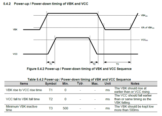
Power supply sequencing is necessary for the proper power-up and power-down of this module. I am looking for assistance in designing this sequence using Texas Instruments (TI) power modules. While researching online, I discovered that the "TPS3808" module can be used to introduce delays. However, I am open to other options and would like to know the optimal design to achieve the power sequencing requirements for the GT-100 module. I have attached the hardware design document of GT-100 module. Here in the document you can browse to page 11 for the power supply sequencing.
Hi Mahima,
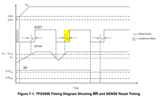
Thanks for the clarification! TPS3808 has only configurable delay pin, which is CT pin that allows to set reset time delay, td.
According to GT-100 datasheet, it seems like you need to set time for both T1 and T2. (As in also seen in the above picture)
I would like to recommend 2 other device that has both CTS and CTR delay pin, which will help you set both the RESET delay and SENSE delay by adding an external capacitor to those pins.
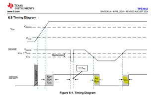
Please check TPS3899 and TPS3842.
They have both small package and low current consumption. The main difference is that TPS3842 can be directly connected to 12V/24V rail since VDD, SENSE and RESET pin can go up to 42V, while TPS3899 can go up to 6V (max)
Hope this helps!
Best,
Sila Atalar
Hi Mahima,
Yes I can help calculating the capacitor values for you. In the datasheet, we provide delay equation for both TPS3899 and TPS3842. What is your required T1 and T2 delay time?
And which device you are more interested?
Best.
Sila
Hi Mahima,
The sense and reset time delay can be set to a minimum value of 50µs and 80µs by leaving the CTS and CTR pins floating respectively, or a maximum value of approximately 6.5 seconds by connecting 10µF delay capacitor.
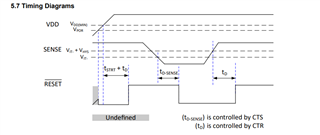
You can either keep it open if you are okay with 50 us and 80 us delay, if not we can add capacitor. In the below, proposal please find 0.1uF cap used as an example use case for the adjustable variant, TPS3899DL01DSER.
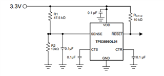
It has open-drain output, and this variant will need a pull up resistor. But we do have push-pull output variants as well. Those are fixed threshold. (TPS3899PL31DSER and TPS3899PL42DSER both of them are fixed variant. The fixed variants include R1 and R2 resistor in to device).
If you are interested with variant, please check our released options.
Hope this helps!
Best,
Sila