


Other Parts Discussed in Thread: LM5137-Q1, LM5137, LM25143
Tool/software:
Hi Team,
We are seeking professional advice on the stability evaluation method for the LM25143-Q1 dropout mode. During the design of LM25143-Q1, the specifications are as follows:
• Output voltage (V_{out}): 16 V
• Input voltage (V_{in}): 9–18 V
• Operating modes:
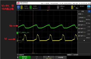
◦ When V_{in} < 16\ \text{V}, the device enters dropout mode, where V_o follows V_i.
◦ When V_{in} > 16\ \text{V}, it operates in the conventional buck mode.
• Design: 2-phase configuration, with 20 A per phase.
Actual Test Results:
• Voltage performance:
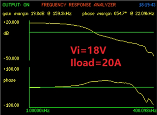
◦ At Vi = 18V, Vo = 16V
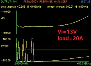
◦ At Vi = 13V, Vo = 12.9V
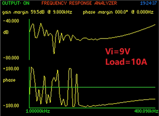
◦ At Vi = 9V, Vo = 8.9V
• Dynamic behavior:
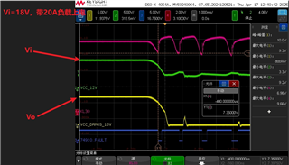
◦ Starting with 20 A or 10 A load at Vi = 18V, 16 V, or 9 V triggers the OCP protection of the Vi input power supply (actual input: 60 A DC source).
• Loop analysis:
◦ When testing the loop at Vi = 9V and 13 V, positive feedback is suspected in the GM (gain margin) measurement.
◦ At Vi = 18V, the phase margin is close to 0° at low frequencies.
| Vi=9V Load=10A | Vi=13V Load=20A | Vi=18V Load=20A |
 |
 |
 |
start up waveform:
Question:
How should we measure the stability of the power supply in this dropout mode?
BR
Adrian

