This thread has been locked.

If you have a related question, please click the "Ask a related question" button in the top right corner. The newly created question will be automatically linked to this question.

UCC24612: Assymetric Vgs LLC

Part Number: UCC24612

Tool/software:

Hi,

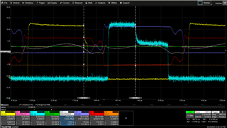
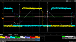
We have an LLC converter with center-tapped secondary output. We are using UCC24612-2 for SR application on both output FETs. One of the FETs is generally seeing longer "Forced Proportional Gate Drive". The layout for both FETs are pretty similar. Please see waveform below:

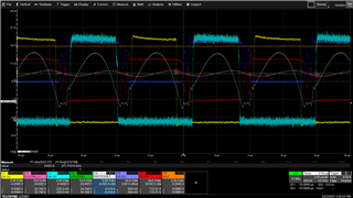
Even at near resonance, we see a similar behavior but difference is less stark


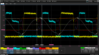
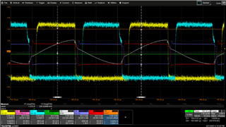
Below resonance, similar:

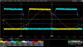
Above resonance, similar:

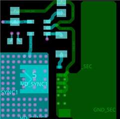
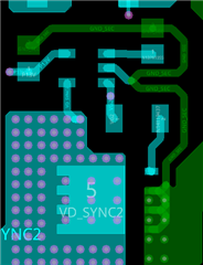
Layout Snips for both FETs:
Q5:

Q4:

Can you suggest what might cause this? And could it be dangerous in any corner case?

  • Hello Shyama, 

    The layouts of the two SR sides seem to be similar enough to not cause significant concern. 

    I think maybe the thermal performance of the two SR pads may be more significantly different, which may account for the symptoms you're seeing.  

    If Q5 gets hotter than Q4, then its resistance goes up and the SR controller may not be able to drop Vgs of Q5 to regulate Vds to -60mV (like it does on Q4).

    The other waveforms are all at higher currents so both FETs get hotter and they seem to have the same gate-drive.  
    I suggest to try using SR FETs with slightly lower Rds(on) to see if both gate-drives show the "proportional" behavior seen with Q4.   

    Regards,
    Ulrich

  • Hi,

    If you see the attached Vgs with I secondary (Both secondary are probed together). Q5 seems to have accurate 50mV (27mohm*1.8A) proportional drive start point. But for Q4 it seems to be starting much earlier.

    Also, if you see closely, there are 2 slopes to change in I secondary. This is seen at higher currents too. Just after diode starts conducting, the slope is very high. After a while, the shape changes to actual I primary sine wave type. Can you comment why that might happen?

  • Hello Shyama, 

    The UCC24612 SR controller for each SR FET Q4 and Q5 are independent of each other.  Each acts on the information presented at its inputs (specifically VD and VS). 

    I can't think of why the Q4 controller starts the proportional drive shaping earlier, on an up-slope of the FET current.
    I can only imagine that the signals seen at its VD and VS inputs and the timing of these signals compared to the previous cycle conform to the conditions necessary to trigger the proportional gate-drive. 

    That would suggest to me that the current path for Q4 is setting up a different Vds voltage than is seen from the current path for Q5, despite how similar the two layouts appears to be in the views provided. 

    Are you able to try my suggestion of trying a higher Rds(on) FET? 

    I can't comment on the step change of current that you are asking about.
    I'm not an LLC expert and cannot answer because I don't know.  

    Regards,
    Ulrich