This thread has been locked.

If you have a related question, please click the "Ask a related question" button in the top right corner. The newly created question will be automatically linked to this question.

LM27762: LM27762 Layout Support

Part Number: LM27762

Tool/software:

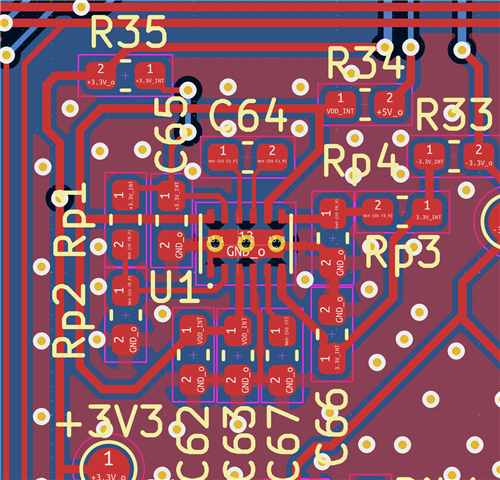
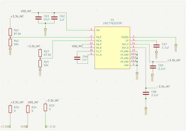
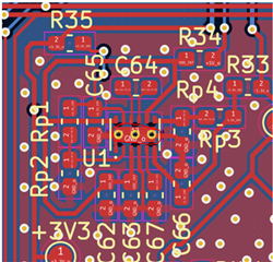
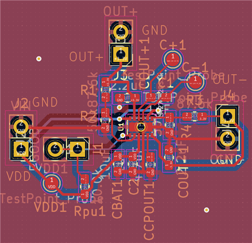
I'm using the LM27762 to step 5V down to +3.3V and -3.3V on a PCB.  For my application I'm using <50mA of current draw from each channel. I've had issues getting this chip to work properly, and made a separate small board to try and get it working. On this board, my +3.3V supply is not working and there are some oscillations present. I understand the layout is critical with these chips so I've attached images of my schematic and PCB for reference. Any help is greatly appreciated!


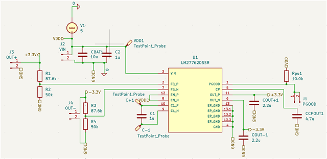
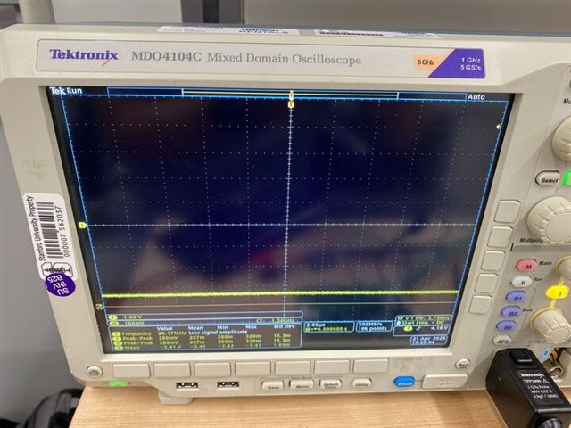
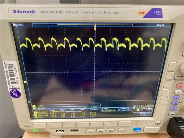
Plot of the +3.3V Supply output:


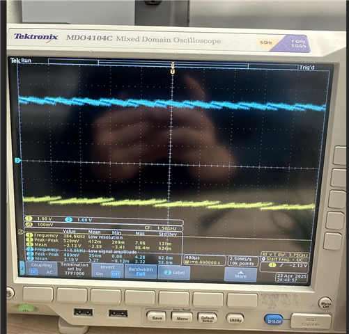
Plot of the -3.3V Supply Output:

  • Hi Eli,

    Thanks for using E2E.

    I think the issue is located on the layout due to insufficient GND connections.

    You should connect both GND planes (Top and Bottom) with a lot of vias in general and especialy near the device GND pins. You should also place additional vias on the GND pins of the capacitors and feedback divider to get a very short GND connection to the device to prevent ringing.

    Best regards
    Sepp

  • Hey Josef,

    Just an update on this, I've gotten a new PCB with this layout. Initially there is some error in the DC output, with the inverting supply at -2.1V and the positive supply at 3.2V with some significant noise. Interestingly, when I short the either supply input to GND (or short them together) for a single instance the supply seems to begin working with the proper DC outputs. I've attached scope screenshots of both conditions and my updated layout, which has extra vias near the caps and feedback resistors to shorten the ground path. Any further ideas you may have are greatly appreciated.

    Eli


  • Hi Elli,

    thanks a lot for the update.

    The -2.1V on the first plot should be -3.3V, correct? 

    Could you please provide the schematic (which is included in your first message) with the additional connections (shorted or connected to GND) you have done to get it working.

    Best regards,
    Sepp

  • Hi Josef,

    Below is the schematic on our current board version. The connections I was referring to are not on the actual PCB, but an external connection I seem to need to make on startup.

    To recap, when I initially turn on the supply it doesn't converge on the proper DC output. If I short either supply to ground momentarily, the supply begins working. So, it's some sort of issue on startup but does not persist after I do this strange fix. Any insights are appreciated.

    Best,
    Eli

  • Hi Eli,

    Josef is on leave for a few days, so i can try to help you out here. 

    Regarding your issue, are the 3 vias on the thermal pad plugged or unplugged? If unplugged, it could be that solder has flown into the vias causing too less solder on the PCB for a good connection to the IC thermal pad. Can you add more solder to these vias and then resolder the device and test?   

    Best regards,

    Varun