A related question is a question created from another question. When the related question is created, it will be automatically linked to the original question.
If you have a related question, please click the "Ask a related question" button in the top right corner. The newly created question will be automatically linked to this question.
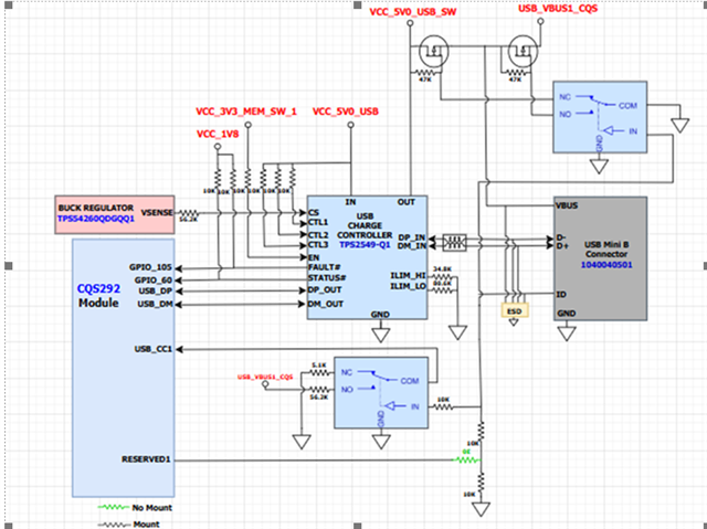
TPS2549-Q1 circuit looks acceptable. I confirmed the current limit resistor matches the calculated values.
I'm not too familiar with the USB ID pin. It appears if ID is low, the SOC's (I think) CC pin will get exposed to 5.1k, telling it to act as host. TPS2549-Q1 will supply up to 1.5A via VCC_5V0_USB_SW net. If ID is high, SOC's CC pin (again, guessing here) is exposed to 56.2k pullup, indicating SOC is USB device and the systems can consume up to 900mA, which is consumed via VBUS1_CQS net.
All of this sounds fine. My only concern is I don't understand how the ID pin behaves. Is it something that can change during an active connection? I'm a little concerned about the timing of the ID pin switching and what will happen if TPS2549-Q1 is set to CDP mode (CTL = 111) and ID is high.
-> Our end product is always in a Host mode. During development we need to make a product in device mode for that we use this logic also we use customized cable to achieve that.
I need your urgent help for below customer query.
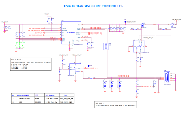
This is just an overview of the schematics, which I have attached.
Query 1 :
Need to confirm that the CDP to SDP logic looks fine or not!!!
Query 2 :
Need to confirm the timing sequence for this CT pin and EN pin is fine, or needs to be verified based on our design
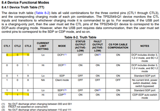
The device as shown will act in CDP-SDP auto switch mode. This effectively means it will act as CDP.
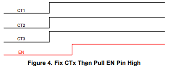
If EN pin goes high while the CTL pins are still low, the device will first handshake as DCP and abide by ILIM_LO, per datasheet truth table 8-2. TPS2549-Q1 actively monitors the CTL pins, so when they go high, it will restart the bus and handshake in CDP-SDP auto switch mode.
If EN comes up after CTL pins are high, it guarantees the first handshake will be from CDP-SDP auto switch mode.
We need a test procedure to validate how we can confirm that this IC can source the (12V - 2.4A)
Also, as per our design,
The first EN pin will get toggled, then after this, the CT pin will get toggled.
As per your suggestion in the above mail, when this EN pin is toggled first, it will be in DCP mode, then after, if all the CT pins are high, it will get switched to the CDP else SDP mode.
Constraint: SDP mode can only source 500mA, our use case is 2.4A, it needs to be sourced
We suspect that a PD-PD communication issue might be present.
Test Plan: We are looking for the test plan to confirm that this controller, operating based on our requirements.
This is not possible with BC1.2 alone. There are 3 types of ports defined by BC1.2
SDP (standard data port): 500mA with USB 2.0 data
DCP (dedicated charging port): 1.5A, no data
CDP (charging data port): 1.5A with data
The only way to get 2.4A is with 2.7V/Divider 3 mode, which by definition does not support USB data. It is similar to DCP. TPS2549-Q1 uses Divider3 mode when configured as DCP.
DCP/Divider 3 and USB2.0 data are mutually exclusive. You can't have both.