A related question is a question created from another question. When the related question is created, it will be automatically linked to the original question.
If you have a related question, please click the "Ask a related question" button in the top right corner. The newly created question will be automatically linked to this question.
Does the LM25018 include a schematic of the soft-start circuit? The datasheet only shows a standalone soft-start circuit, and I’m unsure how to connect it to the chip.
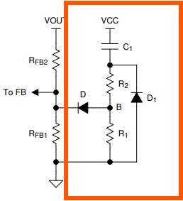
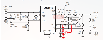
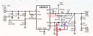
The part shown in the red box is the external soft-start circuit. The diode D should be connected to the FB pin and cap C1 should be connected to VCC pin of the device as shown. RFB1 and RFB2 are the feedback resistor dividers which will be present in the application circuit.